Feeder route
Confirm fiber count, route protection, splice point and future expansion before calculating access-side materials.

Build a coordinated OLT-to-ONT passive network with eight core product families: PLC splitters, fiber distribution boxes, fiber optic adapters, fiber pigtails, fiber patch cords, fast connectors, drop cables and fiber termination boxes. ZION also supports product selection, optical-interface matching and quote-ready BOM planning.
Confirm fiber count, route protection, splice point and future expansion before calculating access-side materials.
Match PLC splitter ratio, insertion loss, connector type and enclosure layout to the optical budget.
Select FAT box or terminal box capacity according to subscriber density, mounting method and maintenance access.
Use FTTH drop cable or pre-terminated drop patch cord based on field labor, routing distance and connector quality control.
| Network layer | Typical start and end | Quantity driver | BOM control |
|---|---|---|---|
| Feeder cable | OLT/ODF to primary split or distribution hub | PON ports, topology, route diversity and growth reserve | Keep feeder fibers traceable by service area; do not size it from subscriber count alone. |
| Distribution cable | Hub or closure to FAT/FDB/NAP | Terminal service areas, splitter placement and spare fibers | Schedule each branch separately so closures, trays and terminal ports reconcile. |
| Drop cable | FAT/FDB/NAP to customer outlet or ONT | Connected premises, actual drop route and installation method | Separate installed drops from future connection stock; use standard length bands where practical. |
Explore the core FTTH product families arranged by recent inquiry demand, from high-frequency connectivity products to field termination and distribution hardware.
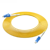
Connectorized fiber assemblies for flexible patching between ODFs, splitter modules, terminal boxes, ONTs and active equipment.
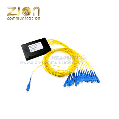
Planar lightwave circuit splitters for centralized or distributed PON architectures, available in multiple ratios and package formats.
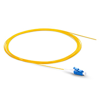
Factory-terminated single-ended fiber assemblies for low-loss fusion splicing inside trays, boxes, ODFs and closures.
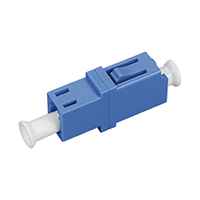
Precision mating adapters that align optical connectors in distribution boxes, termination boxes, panels and equipment interfaces.
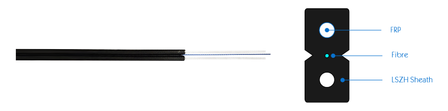
Bend-insensitive flat or round fiber cable for aerial, façade, building-entry and indoor subscriber routes.
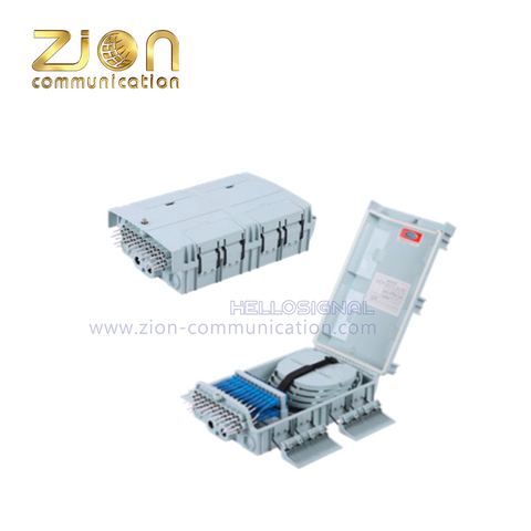
Protected distribution enclosures for splicing, splitting, adapter loading and organized subscriber branch management.
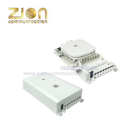
Compact termination enclosures for protected splicing, adapter mounting, bend-radius control and final optical handoff.
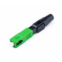
Field-installable connectors for rapid subscriber activation and repair without factory pre-termination of every drop length.
| Application section | Recommended product direction | Selection focus |
|---|---|---|
| Feeder to distribution point | Outdoor fiber cable, splice closure and distribution cabinet products | Fiber count, route protection, cable reserve and future network expansion. |
| PON split point | PLC splitter, splitter module or splitter-integrated terminal box | Split ratio, insertion loss, connector type and optical budget margin. |
| FAT / terminal distribution | Fiber terminal box or FAT box with adapter and splice management | Port capacity, sealing, wall/pole mounting and maintenance accessibility. |
| Subscriber drop route | FTTH drop cable or pre-terminated FTTH drop patch cord | Drop length, pulling force, bend radius, field termination or factory termination. |
| Indoor equipment connection | Fiber patch cord, pigtail and adapter products | SC/APC or LC interface, connector cleanliness, polarity and equipment-side patching. |
Convert the approved split architecture into active feeder and distribution fibers, then add restoration, growth and route-diversity fibers. Select the next available standard cable size only after documenting those inputs. A percentage by itself is not a complete FTTH feeder fiber count rule.
For each closure, list incoming, outgoing, branch, pass-through and splitter-pigtail splices. Required splice tray quantity equals planned splices divided by usable splices per tray, rounded up, plus the project reserve. Confirm cable ports, fiber storage and splitter space separately.
Apply the FTTH spare material ratio by failure and replenishment risk: cable allowance for measured route and handling, extra connectors and small accessories for installation loss, and dedicated restoration stock for long-lead closures or terminals. Do not apply one blanket percentage to every line.
| Planning decision | Recommended method | Check before release |
|---|---|---|
| FTTH spare fiber ratio | Define active fibers first; add named growth, maintenance and restoration fibers, then round to a standard fiber count. | Every spare fiber has a purpose and remains within closure, tray and terminal capacity. |
| Fiber closure capacity | Use the greater constraint from splice count, cable-entry count, stored-fiber volume, splitter accommodation and future branch requirement. | Quoted capacity means usable project capacity, not only the enclosure's headline splice rating. |
| FAT vs FDB vs NAP | Treat names as regional conventions. Compare function: splitter housing, splicing, adapter ports, sealing, mounting and subscriber access. | The schedule states required functions and port configuration instead of relying only on the acronym. |
| FTTH drum length planning | Map each pull section, add installation slack and joint allowance, respect maximum pulling length, drum capacity, transport limits and site sequence. | No planned mid-span joint; each drum is assigned to a route section and has an approved remainder plan. |
| FTTH material optimization | Standardize cable sizes and drop-length bands, consolidate accessories, reconcile BOM to drawings, and reuse acceptable drum remainders on shorter approved sections. | Optimization never removes optical margin, restoration stock or installation slack. |
| Required input | Why it matters | Example information |
|---|---|---|
| Network route section | Prevents one product from being used for all field conditions. | Feeder, splitter point, FAT box, drop route, indoor patching. |
| Fiber count and split ratio | Controls terminal capacity, splitter selection and optical budget. | 1:8, 1:16, 1:32, 1:64, 2/4/8/12/24 fiber drop or distribution route. |
| Connector interface | Ensures compatibility between splitter, terminal box, patch cord and equipment. | SC/APC, SC/UPC, LC/UPC, adapter type and pigtail length. |
| Installation method | Decides whether field termination or pre-terminated products are more suitable. | Aerial drop, wall route, duct route, indoor riser, cabinet-side connection. |
| Packing and marking | Supports distributor stock management and contractor site installation. | Drum length, carton label, cable printing, OEM brand and project code. |
| Sample and document request | Helps confirm product structure before mass procurement. | Datasheet, drawing, sample length, packing photo and available certificates. |
Splitter ratio, connector count and route distance should be reviewed together instead of selecting only by price.
Different subscriber routes may need different strength members, sheath options or pre-terminated assemblies.
FAT box and terminal box capacity should reserve enough ports for maintenance and user growth.
SC/APC, SC/UPC, LC interface and adapter loading should be confirmed before splitter and patch cord quotation.
Freeze homes passed, take rate, PON topology, split locations and mapped route lengths. Schedule OLT-to-ONT components by network node, calculate cable and port quantities, add documented installation and restoration reserves, and reconcile every line against drawings before issuing the RFQ.
A typical passive path includes ODFs, feeder cable, splice closures, cabinets or hubs, PLC splitters, distribution cable, FAT/FDB/NAP terminals, adapters, pigtails, drop cable or pre-terminated drops, customer outlets and patch cords. Add route hardware, splice sleeves, labels, mounting and earthing items as required.
Separate them by function and endpoints: feeder connects the OLT/ODF to a hub or primary split point; distribution connects that point to access terminals; drop connects an access terminal to one premise. Give each segment its own route, construction, fiber count, unit length and reserve rule.
Calculate working fibers from the selected PON and split architecture, then add explicit fibers for growth, maintenance, restoration and any route diversity. Round the result to an available standard cable size and verify that ODF, closure and tray capacities support it.
There is no universal percentage. Set the FTTH spare fiber ratio from growth forecast, repair strategy, route criticality, build phases and the operator's design standard. Record both the percentage and the actual spare-fiber count so the reserve remains visible after rounding.
Count all current and planned splices, cable entries, pass-through fibers, stored fiber and any splitter modules at that exact location. Choose a fiber closure capacity that accommodates the worst of those constraints with the approved expansion margin and compatible cable seals.
Divide the total planned splices in the closure by the usable splice capacity of the selected tray and round up. Add the project reserve, keep splitter or ribbon requirements separate, and confirm the enclosure can physically accept the resulting splice tray quantity.
The acronyms vary by market. FAT usually emphasizes subscriber access termination, FDB emphasizes distribution and splicing, and NAP identifies the network access point. Specify the needed splitter, splice, adapter-port, sealing and mounting functions because product names alone are not reliable selection criteria.
Set separate reserves by material type and risk. Cable needs route, slack and handling allowance; connectors and small hardware need an installation-loss allowance; long-lead enclosures may need restoration stock. State the basis and round to the supplier's pack quantity rather than adding one percentage to the whole BOM.
Reconcile the BOM to the latest route drawings, standardize fiber counts and drop-length bands, assign every drum before shipment, consolidate compatible accessories, and track acceptable remainders for approved short sections. Preserve optical margin, installation slack and restoration stock while optimizing.
Divide drums by continuous pull section, cable type, installation sequence and delivery zone. Add section-specific joint and installation slack, observe drum and transport limits, label each drum to its route, and avoid an unplanned splice simply to use a generic drum length.
For FTTH reel length planning, start with surveyed section length and add approved slack at closures, poles, chambers and equipment. Check pulling tension, bend limits, access points, reel capacity, vehicle handling and installation order, then plan how any usable remainder will be allocated.
Send your route method, fiber count, split plan, connector interface, terminal capacity, packing preference and target schedule. ZION can help review the product direction before sample or quotation discussion.
