
A smart building combines digital networks, automation controls, security systems and life-safety infrastructure. These systems may share telecom rooms, fiber routes and installation pathways, but they do not all use the same topology or cable.
A useful smart building network diagram therefore needs to distinguish the fiber backbone, structured copper network, BMS controllers and field buses, access-control panels and door circuits, CCTV recording paths, fire alarm architecture, logical integration and power dependencies.
Smart Building Topology at a Glance
The most useful high-level diagram begins at the service-provider boundary, passes through an enforced security boundary and core network, and then separates IP endpoints, system controllers, field devices and regulated fire alarm functions.
The fire alarm control panel retains its approved circuits and interfaces; permitted monitoring data may pass to a BMS or integration platform.
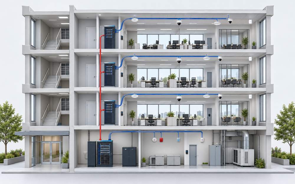
Core principle: converge information where appropriate while preserving the physical, operational and regulatory boundaries of each system.
Three Views of the Same Smart Building
One diagram is rarely sufficient for construction. A complete design normally needs three related views.
Shows entrance facilities, MDF/IDFs, racks, field panels, risers, trays, conduits and the installed cable routes used for length and containment calculations.
Shows subnets, VLANs, controller networks, CCTV recording paths, server communication, gateways and permitted data exchange.
Shows approved HVAC shutdown, smoke control, door release, lift recall, status feedback, supervision and failure response.
Systems may share a fiber cable while using separate fibers or logical networks. Integration through a gateway does not mean the field media are the same.
Layer 1: Building Entrance and MDF
In many project naming conventions, the MDF is the primary communications distribution point for a building or campus. It may contain the service-provider demarcation, core routers and switches, main fiber ODF or patch panels, firewalls, network-management systems, backbone connections, racks, PDUs and UPS support.
Security and BMS servers or gateways may be located there, although modern projects may virtualize them or place them in a data center. Rack space, heat load, power, grounding, pathway capacity, physical security and expansion allowance directly affect the BOM.
For a multi-building campus, the design should evaluate outdoor cable construction, route diversity, lightning exposure, ground-potential differences, duct capacity and the power plan at every remote active-equipment location.
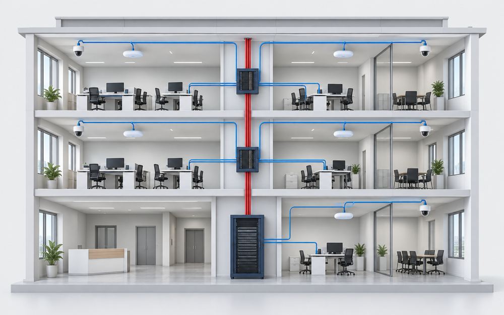
Layer 2: Fiber Backbone Between MDF and IDFs
Fiber is normally the preferred backbone medium between the MDF and floor or zone IDFs because it supports high capacity, longer distances and electrical isolation between active-equipment locations.
Campus links may branch to a secondary building distributor; a genuinely diverse route needs separate failure paths, not only spare fibers.
Each backbone link should define fiber type, fiber count, active-fiber requirements, connector and transceiver interfaces, cable construction, route, panel capacity, splicing, patch cords, optical loss budget, acceptance tests and reserved capacity.
Fiber count should not be selected from switch quantity alone. The backbone may carry ICT, Wi-Fi, CCTV, BMS and access-control traffic, support redundant uplinks or reserve capacity for future systems.
Layer 3: ICT and Structured Cabling
A conventional star topology connects work-area outlets and approved IP devices to the floor IDF. Typical endpoints include computers, printers, IP phones, wireless access points, meeting-room devices, digital signage, selected BMS controllers, IP cameras and access-control panels.
ISO/IEC 11801-1:2017, including its corrigendum and 2025 amendment, defines common generic-cabling requirements. ANSI/TIA-862-C addresses intelligent-building cabling and includes four-pair and single-pair cabling in its scope.
The topology should identify permanent links, patching locations, consolidation points or zone enclosures and direct-attach device connections. These decisions determine outlet, patch-panel, cord and cabinet quantities.
Layer 4: CCTV Topology
An IP CCTV system typically uses PoE access switches in IDFs or security cabinets, with fiber uplinks to the core and separate VMS/NVR and recording-storage functions.
The design needs camera quantity, resolution, frame rate, codec assumptions, individual and total PoE demand, switch ports, uplink capacity, recording bandwidth, storage architecture, cable distance, environmental conditions, UPS requirements and any required redundant paths.
Recording bandwidth and retention should be calculated from documented camera profiles or validated bit-rate assumptions. Resolution alone is insufficient because codec, frame rate, scene activity, image settings, analytics and retention policy can materially change storage demand.
Fiber is especially useful for remote gates, parking areas, separate buildings and high-EMI routes. A fiber link still requires a complete power plan for the remote camera or PoE switch.
Layer 5: Access-Control Topology
Access control often has two connection layers: an IP, serial or proprietary link between the central platform and door controllers, followed by dedicated field wiring from each controller to readers, locks, door contacts and exit devices.
The approved fire alarm interface acts on the documented emergency-release path; its exact relationship to the controller or lock power supply depends on the approved design.
For each door, define controller location, reader protocol and cable, lock type, voltage, current, power source, fail-safe or fail-secure behavior, door contact, request-to-exit function, emergency release, voltage-drop limits, supervision and battery backup.
For new designs, consider OSDP Secure Channel between the controller and compatible readers. OSDP supports bidirectional communication and supervision, while Secure Channel adds AES-128 protection. Secure mode, key management, addressing, topology and verified interoperability must be commissioned. Legacy Wiegand does not provide the same supervision or protected communication.
Depending on the fire strategy and local code, release may act through a listed interface, the access controller, a lock power-supply input or direct interruption of lock power. The drawing should show the actual release path and status feedback.
Layer 6: BMS Topology
A building management system often combines an IP supervisory layer with one or more fieldbus layers. BACnet is standardized in ANSI/ASHRAE 135 and ISO 16484-5. ANSI/ASHRAE 135-2024 superseded the 2020 edition, and ISO 16484-5:2026 superseded the 2022 ISO edition.
BACnet/IP or BACnet/SC may serve the IP layer; BACnet MS/TP, Modbus RTU, KNX TP and point-to-point I/O may serve field layers.
- BACnet/IP: BACnet communication over an IP network, commonly carried on Ethernet; the name does not imply encryption or authentication.
- BACnet/SC: a TLS-secured WebSocket data link for BACnet on IPv4 or IPv6, with certificate and hub design requirements.
- BACnet MS/TP: an RS-485 trunk with approved topology, termination and device loading.
- Modbus RTU: typically RS-485, with implementation limits defined by the participating equipment.
- KNX TP: a dedicated twisted-pair bus with KNX topology and power requirements.
- KNX IP: an IP-based backbone or interface; KNX IP Secure and KNX Data Secure must be specified and commissioned where required.
- Analog and digital I/O: point-to-point control or instrumentation wiring.
Every segment should state the protocol, data link or transport and physical medium. “BACnet cable” is not a sufficient cable specification.
Layer 7: Fire Alarm Topology
A fire alarm system is a life-safety system with its own control panel, circuits, power supplies, monitoring and code obligations. The diagram should keep its architecture visible rather than hiding fire devices inside a general LAN cloud.
Permitted status monitoring may be shared with a BMS, but monitoring an alarm point is not the same as implementing an approved emergency-control function.
The topology and BOM should identify circuit arrangement, device and isolator placement, alarm, fault and supervisory interfaces, circuit-integrity requirements, power and battery calculations, segregation, pathways, cause-and-effect testing and handover records.
NFPA 72 is relevant only where the applicable edition has been adopted; the current published edition is NFPA 72 (2025). IEC 60331-2:2018 defines a cable test method for circuit integrity under fire with mechanical shock. Passing that test does not by itself establish the complete cable classification, circuit-survivability method or project approval.
Integration Does Not Mean One Flat Network
Smart-building platforms often combine dashboards, alarms, energy data and maintenance information. That does not require every subsystem to occupy one unrestricted LAN.
Use defined gateways, APIs, firewalls, controlled routing and read-only interfaces where control is unnecessary.
Document addressing, permitted flows, device ownership, update responsibility, logging and incident response.
Maintain asset inventory, unique credentials, certificates, tested backups, supported firmware and end-of-life plans.
Specify what local controllers, doors, cameras and gateways do when servers, uplinks or power sources fail.
VLANs are useful, but a VLAN label alone is not a complete security or resilience design. Inter-zone traffic should pass through an enforced boundary with documented permitted flows, and building devices should not be exposed directly to the public internet. NIST SP 800-82 Rev. 3 provides relevant OT-security guidance and explicitly includes building automation and physical access-control systems.
Where to Use Fiber and Where to Use Copper
The table below is a project-planning starting point. Approved equipment manuals, adopted standards and the project specification determine the final medium and cable construction.
| Link | Typical medium | Design reason |
|---|---|---|
| MDF to floor IDF | Fiber | Capacity, reach, uplink flexibility and electrical isolation. |
| Building-to-building backbone | Outdoor or indoor/outdoor fiber | Distance, lightning and ground-potential separation, and route flexibility. |
| IDF to work-area outlet | Cat6 or Cat6A | Standards-based horizontal structured cabling. |
| IDF to IP camera or AP | Cat6 or Cat6A PoE link | Data and power over one channel within approved limits. |
| Remote camera cluster | Fiber plus remote power or PoE switch | Long distance, outdoor exposure or electrical noise. |
| BMS IP controller | Cat6/Cat6A or fiber uplink | Ethernet connection selected for the network design. |
| BMS RS-485 trunk | Approved impedance-controlled twisted pair | Fieldbus electrical and topology requirements. |
| KNX TP line | KNX-approved bus cable | Bus power and KNX physical-layer requirements. |
| Door controller to field devices | Protocol, lock-power and monitored-I/O cable | Reader data, voltage drop, supervision and control functions. |
| Fire alarm circuits | Listed or approved fire alarm cable/system | Life-safety circuit, survivability and local-code requirements. |
Redundancy and Availability
Define availability by service rather than copying one redundant topology everywhere. Check redundant core equipment, diverse fiber routes, UPS or battery duration, controller autonomy, door behavior, local CCTV recording and the independence of essential fire alarm functions.
From Network Topology to Project BOM
Every connection in the topology should generate equipment, cable, termination, power and test requirements in the BOM.
| Topology element | BOM output |
|---|---|
| MDF-IDF fiber link | Fiber cable, ODF ports, pigtails or adapters, splice protection, patch cords and test scope. |
| Copper horizontal link | Bulk cable, patch-panel port, outlet or module, cords, labels and certification tests. |
| PoE camera or AP link | Category cable, PoE port, patching, power-budget allocation and environmental accessories. |
| RS-485 trunk | Bus cable, terminals, termination, controller ports and shield-grounding provisions. |
| Access-controlled door | Reader, lock, contact and REX cables, controller capacity, enclosure, PSU and battery. |
| Fire alarm loop | Approved cable, devices, isolators, modules, accessories and test records. |
| Redundant path | Separate route quantity, termination capacity, active ports, power and failure-domain checks. |
Common Topology Mistakes
This hides floor distribution, distance limits, controller layers and real termination points.
IP networks, RS-485, KNX and point-to-point field wiring need separate labels.
Approved life-safety circuits and emergency-control interfaces must remain visible.
PoE, lock power, controller power, fire-panel batteries and remote UPS affect cable and equipment selection.
Spare strands in one cable do not protect against a cable cut or shared pathway failure.
Outdoor ducts, wet locations, EMI, elevator spaces and fire-rated routes may require different construction.
Smart Building Topology Design Checklist
- Locate building entrances, MDFs, IDFs and field panels.
- Separate backbone and horizontal links.
- Define fiber type, count, termination and route.
- Define copper category, shielding and PoE demand.
- Show camera links and recording paths.
- Separate access-control IP links from door wiring.
- Identify BMS IP, RS-485, KNX and I/O layers.
- Keep fire alarm circuits independent and clearly labeled.
- Show gateways and approved supervised interfaces.
- Document power, UPS and battery dependencies.
- Define segmentation and permitted system traffic.
- Distinguish spare fibers from diverse routes.
- Check distance and environmental limits.
- Map every connection to a BOM and test requirement.
Frequently Asked Questions
What is the main backbone of a smart building network?
In many commercial projects, fiber connects the MDF to floor or zone IDFs, while structured copper connects the IDFs to IP endpoints. The final architecture depends on building size, distance, availability and project standards.
Can BMS, CCTV and access control use the same switches?
They can use shared network infrastructure when approved by the project design and cybersecurity policy. Capacity, PoE, availability, ownership, segmentation and failure behavior still need to be evaluated for each system.
Is every BMS device connected by Ethernet?
No. Supervisory controllers may connect through IP networks using BACnet/IP, BACnet/SC or vendor protocols, while field devices may use BACnet MS/TP, Modbus RTU, KNX TP, analog signals or dedicated control wiring.
Why is fire alarm shown separately?
Fire alarm is a regulated life-safety system with dedicated control, circuits, power and supervision requirements. Integration with BMS or other systems must not obscure its independent architecture.
When should fiber be used for CCTV?
Fiber is useful for long distances, remote buildings, outdoor areas, high-EMI routes and high-capacity switch uplinks. The remote equipment still requires an appropriate power source.
Does having two fibers provide redundancy?
Not necessarily. Two fibers in one cable or two cables in one pathway can share the same failure point. True route resilience requires analysis of pathways, rooms, power and active equipment as well as cable count.
References
- ANSI/TIA-862-C: Structured Cabling Infrastructure Standard for Intelligent Building Systems.
- ANSI/TIA-568.2-E: Balanced Twisted-Pair Telecommunications Cabling and Components Standard.
- ISO/IEC 11801-1:2017, including Amendment 1:2025.
- ANSI/ASHRAE Standard 135-2024 — BACnet.
- ISO 16484-5:2026 — BACS data communication protocol.
- BACnet/SC overview.
- KNX topology and supported media.
- Open Supervised Device Protocol (OSDP).
- NFPA 72 (2025): National Fire Alarm and Signaling Code.
- IEC 60331-2:2018 — circuit integrity under fire with mechanical shock.
- IEEE 802.3-2022 — Ethernet and power over selected twisted-pair PHYs.
- NIST SP 800-82 Rev. 3 — Guide to Operational Technology Security.
Prepare the Cable Package for Your Smart Building Project
Submit the approved topology, BOQ or cable schedule together with cable types, quantities, route environments, required standards, fire-performance requirements, destination and delivery window. ZION can support cable specification matching, product documentation, packaging coordination and quotation.
Request Project Support


