
1. Direct answer: which underwater communication method should you choose?
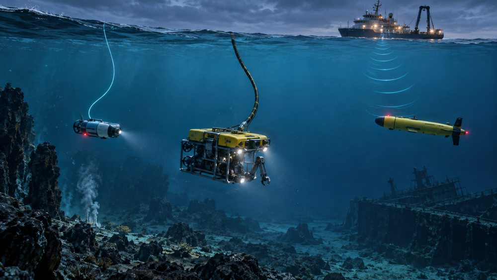
When a battery-powered platform needs high-rate data and lower drag than a conventional powered umbilical.
When a work-class ROV needs continuous topside power together with high-rate optical data.
When untethered movement, low-rate telemetry, positioning support, or emergency commands are the priority.
When the mission needs both high-bandwidth operation and a low-rate path for monitoring or recovery after tether loss.
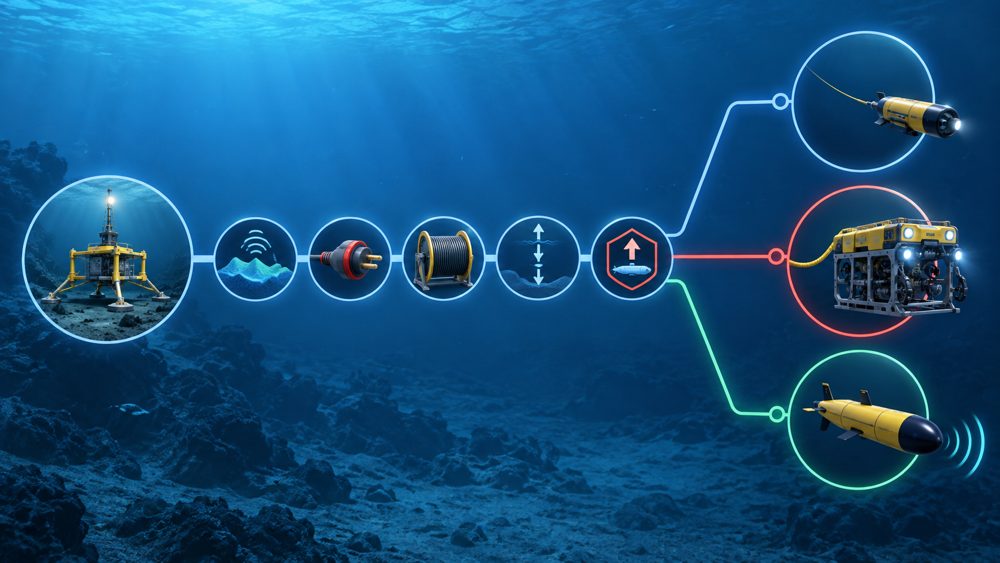
The selection should start with required payload throughput, power source, acceptable tether drag, end-to-end latency, operating range and depth, and the safe vehicle response after loss of the primary link.
2. Engineering comparison
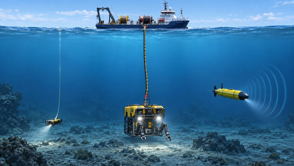
The table compares system roles rather than treating the word “copper” as a single data standard. A copper cable may carry power, serial data, Ethernet, or a modem signal, while an electro-optical umbilical may contain both copper conductors and optical fibers.
| Dimension | Fiber micro-tether | Copper or electro-optical umbilical | Acoustic link |
|---|---|---|---|
| Connection | Wired | Wired | Wireless; no tether |
| Typical role | Live video, sonar, sensor data, teleoperation | Power, control, and data | Commands, status, positioning, low-rate data, backup |
| Throughput | Defined by transceivers, protocol, and optical budget; Gigabit Ethernet is demonstrated | Varies with conductor, modem, interface, and length | Common products range from tens to thousands of bit/s |
| Delay | Low; end-to-end delay includes terminal and application processing | Low; system dependent | About 0.67 seconds one-way per kilometre from propagation alone |
| Power delivery | None in a fiber-only tether | Copper conductors can deliver power | None; local platform power required |
| Mechanical effect | Low drag, not zero drag; bend, abrasion, payout, and snag risks remain | Usually larger, heavier, and higher-drag; may be load-bearing | No cable drag; transducer placement and platform noise matter |
| Typical failures | Break, tight bend, abrasion, connector leakage, payout or terminal fault | Conductor, insulation, connector, water-ingress, voltage-drop, or mechanical fault | Multipath, blockage, bubbles, noise, Doppler, attitude, or fading |
3. What real underwater systems show
WHOI's Nereid Under Ice (NUI) hybrid vehicle provides a useful like-for-like example. Its communications-only micro-tether supported Gigabit Ethernet over a listed 20 km length. On the same vehicle, a low-frequency acoustic link provided 20–300 bps at 20 km, while a high-frequency acoustic link provided 300 bps over 1–5 km.
The example explains why fiber supports video and interactive operation while acoustics can preserve low-rate monitoring and recovery communication. It is not a universal acoustic ceiling. WHOI lists 80–5,400 bps packet burst rates for its Micro-Modem, while Sonardyne lists 200–9,000 bps for the Modem 6 family. Sustained throughput depends on range, depth, frequency, transducers, noise, multipath, motion, and protocol overhead.
4. When a fiber micro-tether is the better fit
Fiber is usually preferred for live HD video, high-volume sonar or sensor data, interactive teleoperation, and electrically noisy environments. The optical medium is immune to electromagnetic interference, although terminals and vehicle power electronics still require proper EMC engineering.
ZION's underwater fiber optic spool page lists G.657.A2 single-mode fiber, aramid reinforcement, a PVC sheath, 0.5/0.65 mm cable diameters, and 1–30 km length options. G.657.A2 identifies bend-loss-insensitive single-mode fiber characteristics; project qualification still needs depth, pressure, water-resistance, bend, tension, and payout data for the complete cable and deployment system.
The page lists attenuation of ≤0.35 dB/km at 1310 nm and ≤0.25 dB/km at 1550 nm. Over 30 km, fiber attenuation alone can therefore reach 10.5 dB or 7.5 dB before connectors, splices, bends, temperature, ageing, and engineering margin are added.
5. When copper or an electro-optical umbilical is the better fit
If the vehicle requires continuous power from the support vessel, copper conductors are normally essential. Work-class ROV systems commonly integrate high-voltage conductors, optical fibers, strength members, and protective layers in one umbilical.
The practical categories are therefore:
- a communications-only fiber micro-tether;
- a cable using copper for data and/or power; and
- an electro-optical umbilical containing both copper conductors and optical fibers.
A communications-only fiber spool is not a powered umbilical. A platform using this architecture needs enough onboard energy for the mission plus reserve for link-loss recovery. An electro-optical umbilical adds weight and drag but can support long-duration, power-intensive intervention tasks.
6. When acoustic communication is the better fit
Acoustic communication is well suited to untethered AUV operations, long-range low-rate telemetry, positioning support, and emergency control after a fiber break. Its limitations extend beyond nominal bandwidth:
- Sound travels at approximately 1,500 m/s, producing about 0.67 seconds of one-way propagation delay per kilometre.
- Links are commonly half-duplex; acknowledgements, polling, error correction, and retries reduce effective throughput.
- Shallow-water multipath, surface bubbles, propulsion noise, transducer shadowing, and vehicle attitude can change performance.
- A modem's serial port speed or packet burst rate is not the same as sustained application payload throughput.
The acoustic link budget and protocol timing should be evaluated for the actual water depth, horizontal or vertical path, platform noise, transducer geometry, and required message size.
7. Hybrid communication and link-loss behavior
A hybrid design can use fiber as the high-bandwidth primary path and acoustics for health reports, compact commands, positioning support, or recovery after tether loss. Adding a second modem does not by itself create a safe backup architecture.
Define loss-of-link thresholds, heartbeat timing, degraded modes, and recovery attempts.
Design compact acoustic messages for heading, depth, thrust, state, position, and abort commands.
Specify whether the platform holds position, continues a safe mission segment, returns, or ascends.
Set timeouts and autonomous safety behavior for loss of both fiber and acoustic communication.
8. Procurement and RFQ checklist
A useful RFQ should define the complete communication system, not only cable length or connector type.
- Required protocol, payload throughput, end-to-end latency, and packet-loss criteria.
- Transmitter output, receiver sensitivity, connector loss, and full optical power budget.
- Operating depth, pressure-test method, immersion duration, and sealing design.
- Static and dynamic bend radius, allowable tension, payout tension, and turning radius.
- In-water weight or buoyancy, drag, diameter tolerance, abrasion, and snag exposure.
- Connector model, depth rating, mating life, and field-termination method.
- Disposable, semi-recoverable, or reusable deployment and the recovery plan after breakage.
- Exact component, certificate number, test report, and scope behind each compliance claim.
9. Frequently asked questions
Is underwater fiber always better than acoustic communication?
No. Fiber supports far higher throughput and low link delay, but it creates a physical tether and a fiber-only link cannot power the vehicle. Acoustics preserve untethered movement and long-range low-rate communication.
Can a fiber-only micro-tether power an ROV or AUV?
No. A pure optical tether carries data, not electrical power. The platform needs onboard batteries or a separate power path. Continuous topside power normally requires copper conductors in an umbilical.
Does a 30 km fiber spool guarantee a 30 km communication link?
No. The complete optical power budget must include fiber attenuation, connectors, splices, bends, temperature, ageing, and engineering margin. Route geometry and reserve fiber can also reduce usable vehicle reach.
What should be checked before specifying an acoustic backup link?
Confirm range, depth, frequency, payload throughput, transducer placement, platform noise, protocol timing, power consumption, and the vehicle states used for link loss, hold, return, or recovery.
10. Technical references
- ZION underwater fiber optic spool specifications and options
- ITU-T G.657: bend-loss-insensitive single-mode optical fibre and cable
- WHOI: Nereid Under Ice fiber and acoustic communication system
- WHOI Micro-Modem data rates and system throughput
- Sonardyne Modem 6 acoustic data rates
- WHOI: electro-optical umbilical example on ROV Jason
Prepare the communication architecture for your underwater project
Share the vehicle type, mission range and depth, payload throughput, power source, connector preference, deployment method, and link-loss strategy so the fiber path and terminal configuration can be reviewed against the complete system requirement.
Request Project Support


