
What does G.657.A2 actually specify?
The current ITU-T G.657 (08/2024) describes G.657.A2 as category A fiber appropriate for a minimum design radius of 7.5 mm. Category A attributes are a subset of G.652.D, with the same transmission and interconnection properties.
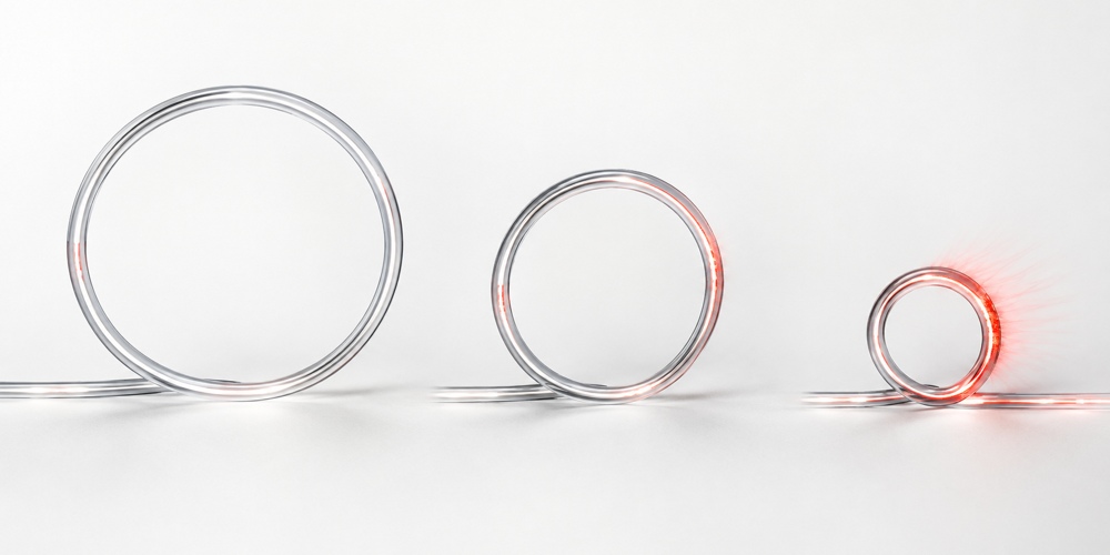
The Recommendation specifies macrobending-loss limits for uncabled fiber. The selected conditions below show that the loss limit increases as the radius becomes smaller and is higher at 1625 nm than at 1550 nm.
| Bend condition | Maximum loss at 1550 nm | Maximum loss at 1625 nm |
|---|---|---|
| 15 mm, 10 turns | 0.03 dB | 0.10 dB |
| 10 mm, 1 turn | 0.10 dB | 0.20 dB |
| 7.5 mm, 1 turn | 0.50 dB | 1.00 dB |
Compact winding involves more than bend radius
Winding and payout can introduce two different optical loss mechanisms. Macrobending follows a visible curved path, such as a small spool core or a tight outlet turn. Microbending comes from small local deformations caused by layer pressure, surface irregularities, thermal contraction or bonding processes.
Review spool-core radius, outlet geometry, routing changes and the wavelengths used by the link.
Review winding pressure, jacket and reinforcement behavior, bonding method, temperature and surface finish.
G.657.A2 primarily improves macrobending performance. Compactness therefore needs finished-spool and dynamic-payout validation, not only a fiber designation.
Why 7.5 mm is not a finished-cable guarantee
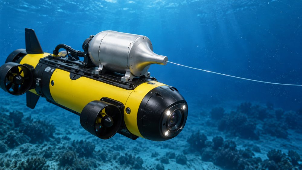
ZION's underwater fiber optic spool page lists G.657.A2 fiber with aramid reinforcement and a PVC sheath. The allowable static bend radius, dynamic bend radius and bend-under-tension limit depend on this complete construction.
A project specification should separately define the finished micro-cable's static and dynamic bend radii, added attenuation at specified tension, temperature and payout speed, and residual attenuation or physical damage after testing. IEC 60794-1-111:2023 provides a cable bend-test method, while the mandrel diameter, cycles and acceptance criteria remain product-specific.
How should ZION's published values be interpreted?
The public specifications list two nominal cable diameters, two linear masses and two tensile-force values. They are useful for early screening, but each value should be linked to a model code and a defined test basis before design release.
| Published item | Engineering interpretation | Project confirmation |
|---|---|---|
| 0.50 / 0.65 mm | Nominal outside diameter affecting capacity and payout behavior | Tolerance and ordered model |
| 248 / 430 g/km | Linear mass, not complete assembly weight | Canister, leads, connectors and submerged buoyancy |
| >150 / >200 N | Published tensile-force values, not stress in pascals | Breaking, short-term or acceptance load; working tension |
The force values must not automatically be used as continuous payout tension or termination capacity. IEC 60794-1-101:2024 defines a tensile-test method, but load levels, duration, gauge length and pass/fail criteria must be stated in the cable or project specification.
G.657.A2 does not establish underwater suitability
G.657 addresses optical transmission and bending characteristics; underwater performance depends on additional mechanical and environmental evidence.
- Rated depth, hydrostatic pressure and pressure cycling
- Water absorption, hydrolysis, seawater and abrasion resistance, plus intended immersion duration
- Canister sealing and pressure ratings for connectors or penetrators
- Submerged linear mass, buoyancy, drag and transient maneuver loads
- Payout-speed range, outlet geometry, minimum tension, jam load and anti-tangle performance
- Temperature cycling, loaded-spool insertion loss, OTDR records and mission-length optical power budget
These conditions turn a general fiber choice into a testable underwater system specification.
Evidence to request for procurement or customization
Ask for records that match the ordered model, cable length and complete configuration:
- Fiber and finished-cable attenuation, plus loaded-spool insertion loss or OTDR records.
- Finished-cable static and dynamic bend radii with test conditions.
- Breaking force, short-term and continuous allowable tension, test method and safety factor.
- Prototype payout testing at the specified temperature, speed and tension.
- Rated depth, pressure-test and immersion conditions, and the water-tight connection design.
- Mounting envelope, payout direction, complete mass, center of gravity and interface definition.
Conclusion
G.657.A2 is a sound transmission medium for compact underwater fiber payout systems because it reduces macrobending-loss risk at small radii while retaining G.652.D compliance. The 7.5 mm value should be treated as a fiber design and macrobending-performance scale, not as a universal finished-cable or spool guarantee. System suitability is demonstrated across the fiber, micro-cable, winding pack, payout structure and mission environment.
FAQ
Does G.657.A2 mean the finished micro-cable can always bend to 7.5 mm?
No. The 7.5 mm value is the minimum design radius associated with G.657.A2 and its uncabled-fiber macrobending conditions. The finished micro-cable requires separately specified static, dynamic and bend-under-tension limits.
Are the published >150 N and >200 N values continuous payout tensions?
Not without a defined test basis. The supplier should identify whether each value is breaking force, short-term allowable load or an acceptance-test load, then specify continuous working tension separately.
Does G.657.A2 establish underwater or deep-sea suitability?
No. Underwater suitability also depends on rated depth, hydrostatic pressure, immersion conditions, material resistance, sealing, connectors, payout mechanics and complete-system validation.
References
Prepare a testable underwater payout specification
Share the platform, mission length, rated depth, payout speed, optical interfaces and acceptance requirements so the cable, spool and terminal configuration can be reviewed together.
Request Project Support


