Cable Selection Matrix for Campus Security Systems
Translate each security function into a measurable cable requirement before issuing an RFQ. The terms below are useful only when they are tied to the approved equipment, route and acceptance criteria.
| System or search term | Typical planning basis | Items to verify |
|---|---|---|
| OSDP reader cable / RS485 cable for OSDP | Balanced twisted-pair RS-485 data channel with separate or composite reader-power conductors. | Impedance, resistance, capacitance, shield, topology, termination, length, fire rating and device instructions. |
| Wiegand cable | Dedicated point-to-point multi-conductor reader connection. | Conductor count, reader power, route length, controller pinout and migration needs. |
| IP CCTV cable | Solid-copper Cat6/Cat6A for compliant copper channels; fibre for backbones, distance or isolation. | Bandwidth, PoE class, channel length, bundle heating, outdoor rating, surge exposure and switch budget. |
| Lock and door-monitoring cable | Power conductors sized by current and voltage drop; supervised low-current pairs for monitoring. | Inrush current, fail-safe/fail-secure operation, fire release, conductor size and end-of-line supervision. |
| Campus fibre backbone | OS2 or approved multimode fibre between buildings and remote security cabinets. | Fibre count, diversity, armour, indoor/outdoor transition, loss budget, ODF and spare capacity. |
1. Start With Security Zones and Threat Boundaries
Map the campus before choosing cable:
- Public boundary and visitor entry
- Vehicle gates and guardhouses
- Staff entrances
- Loading and delivery areas
- Offices and security control room
- Data halls and meet-me rooms
- UPS, battery and electrical rooms
- Generator and fuel areas
- Roof, yard and perimeter cameras
- Telecom entrance rooms
- Inter-building pathways
- Emergency exits and fire-compartment interfaces
For each zone, document the device, controller, switch, power source, recording destination, communication path, expected retention, failure response, and maintenance access.
Security functions should also be classified by criticality. A failed office camera and a failed mantrap reader do not create the same risk. Critical paths may need local controller intelligence, redundant servers, dual network paths, UPS-backed switches, diverse fibre routes or spare conductors.
2. Split Access Control Into Separate Circuits
A typical controlled door can include:
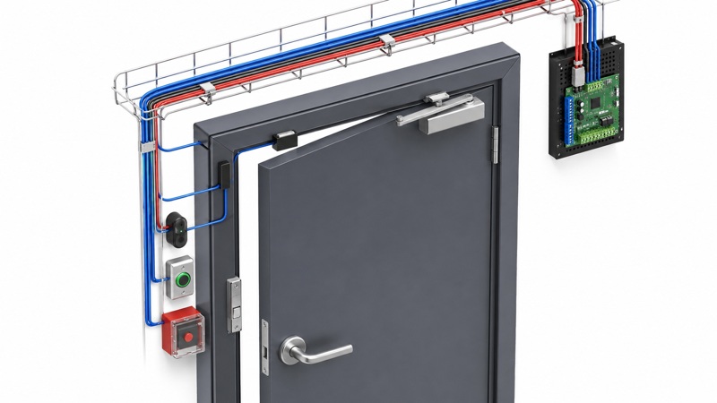
- Card or biometric reader
- Door controller or interface module
- Electric strike, maglock or motorized lock
- Door-position switch
- Request-to-exit device
- Break-glass or emergency release
- Sounder or indicator
- Intercom
- Fire alarm interface
These circuits have different data, voltage, current, conductor-size and life-safety requirements. A composite access-control cable may simplify pulling, but every component still needs to be electrically correct and accepted by the equipment manufacturer and AHJ.
Reader communication
Legacy Wiegand commonly uses multiple conductors in a point-to-point arrangement and lacks the security and bidirectional features available in modern OSDP implementations. SIA describes OSDP as a communication protocol for interoperable access-control devices and emphasizes Secure Channel for encrypted, authenticated communication.
Where supported by the approved reader and controller, specify:
- OSDP-capable equipment
- Secure Channel enabled after commissioning
- Correct RS-485 cable construction
- Addressing and baud-rate plan
- Bus topology and termination
- Shield bonding and grounding
- Unique key-management process
- Verified product compatibility
Do not assume that using an RS-485 cable automatically enables OSDP security. Secure Channel is a system configuration and key-management requirement.
Lock power
Lock circuits are driven by voltage drop and inrush or operating current. Confirm:
- Lock type and fail-safe/fail-secure behavior
- Nominal and worst-case current
- Supply voltage
- Route length
- Conductor size
- Local or centralized power supply
- Battery backup
- Fire alarm release logic
- Voltage at the lock under worst-case load
Do not use reader-data conductors to carry lock power unless the approved composite cable and device design explicitly allow it.
Door monitoring and release
Door contacts and request-to-exit devices may use low-current circuits but still require correct conductor count, supervision, routing and identification. Emergency release and fire-alarm interfaces must follow local life-safety and egress rules. Security availability must never override required safe egress.
3. Choose OSDP Cable as an RS-485 Channel
OSDP reader communication is based on RS-485. The cable schedule should state:
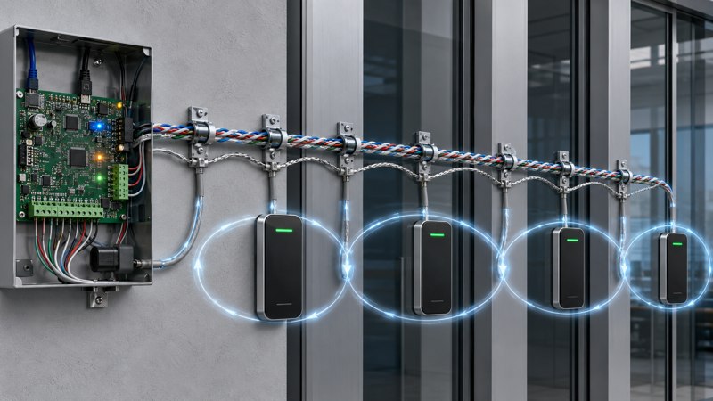
- One balanced twisted pair for data as required by the system
- Characteristic impedance required by the controller/reader manufacturer
- Conductor size and resistance
- Shield and drain-wire requirement
- Rated voltage and temperature
- Overall sheath and fire rating
- Indoor/outdoor and UV performance
- Maximum segment length and device count
- Topology, stubs and termination
SIA's implementation guidance recommends Secure Channel and stresses correct configuration. Use OSDP Verified products where the project requires verified interoperability. Cable is only one element; reader, controller, firmware and commissioning practices must work together.
4. Design CCTV Around Bandwidth, Power and Distance
For every camera, record:
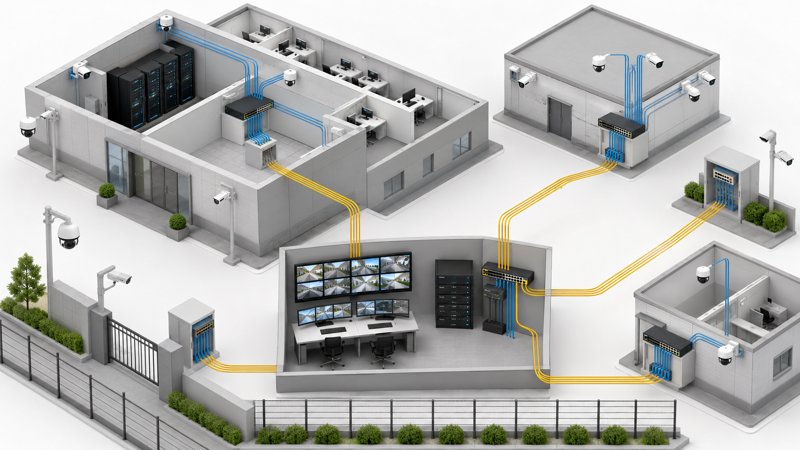
- Resolution, codec and frame rate
- Main and secondary streams
- Analytics and metadata
- Audio, PTZ, heater, IR and illuminator loads
- PoE class and worst-case power
- Copper channel length
- Switch location and port budget
- UPS runtime
- Recording destination and retention
- Environmental enclosure and temperature
- Surge and lightning exposure
Copper Ethernet and PoE
Cat6 or Cat6A copper cabling is commonly used for IP cameras within an engineered Ethernet channel. The selection should consider bandwidth, PoE power, insertion loss, DC resistance, resistance unbalance, bundle heating, ambient temperature, pathway fill and future replacement.
IEEE 802.3af introduced standardized powering over the Ethernet interface, and IEEE 802.3bt expanded standardized higher-power PoE. The camera and switch must negotiate or support the same applicable PoE technology. A high-wattage camera with heaters, IR, PTZ or edge computing may require more than a basic PoE port can deliver.
Avoid selecting cable only by category. Confirm:
- Solid copper conductors, not copper-clad substitutes for permanent PoE channels
- Category and channel standard
- Conductor gauge and DC performance
- Shielding and bonding where required
- CPR, LSZH, plenum or riser requirement
- Outdoor, UV and water-blocked construction where needed
- Maximum ambient temperature and bundle size
- Patch cords, connectors and patch panels of a compatible category
Fibre for distance, isolation and campus backbones
Use optical fibre where copper distance, EMI, electrical-potential difference, lightning exposure or campus architecture makes copper unsuitable. Common applications include:
- Guardhouse to main security building
- Perimeter camera aggregation cabinets
- Links between data halls
- Remote electrical yards
- Redundant paths to the security operations center
- High-bandwidth video aggregation
Select OS2 or multimode fibre according to equipment, reach, bandwidth and upgrade plan. Define fibre count, spare fibres, indoor/outdoor transition, armour, duct, splice closure, ODF, patch cords, connector type and testing.
5. Verify ONVIF Conformance, Not Just the Logo
ONVIF profiles define standardized feature sets for IP-based physical-security products.
- Profile T supports advanced IP video streaming, including H.264/H.265-related capabilities, imaging settings, metadata and alarm events within its profile requirements.
- Profile G addresses recording and retrieval.
- Profile M addresses analytics metadata and events.
- Profile A addresses access-control configuration such as credentials, schedules and rules.
ONVIF states that only registered products conformant to a profile are considered ONVIF conformant. Procurement should verify the exact camera, recorder, VMS, access-control product and firmware against the ONVIF conformant-products database or project-approved evidence.
Cable does not create ONVIF interoperability, but insufficient bandwidth, unstable PoE or poor installation can make conformant products perform badly.
6. Plan Resilient Security Pathways
Security cabling should be coordinated with the data center's operational resilience plan:
- Avoid a single tray or riser for all critical cameras and controllers
- Separate redundant fibre paths where the risk analysis requires it
- Place security switches and controllers in protected, maintainable locations
- Provide UPS-backed power for selected network and controller equipment
- Keep local door operation safe during upstream network loss
- Segment networks and limit broadcast/failure domains
- Reserve fibre, rack space, switch ports and pathway capacity
- Protect outdoor cabinets against heat, dust, moisture and tampering
- Document isolation points for planned maintenance
Tier classification does not automatically prescribe the security topology. The owner, security consultant and operations team must define which functions need redundancy and how failures are handled.
Shared Pathways and Power-Circuit Separation
Access-control and CCTV circuits can share a pathway only when the adopted code, project specification, containment capacity, electromagnetic compatibility, firestopping and maintenance strategy permit it. A shared access control CCTV pathway should retain clear cable identification and service grouping. Critical systems should use diverse routes when one tray, duct or riser would create an unacceptable common failure point.
Define security cable separation from mains and high-current circuits on the drawings instead of relying on a generic site rule. Use dedicated low-voltage containment where required, apply approved barriers, maintain the spacing required by the local code and project standard, and cross power circuits at approximately 90 degrees where separation cannot be maintained. Coordinate bonding, lightning protection and metallic containment with the electrical engineer and AHJ.
7. Coordinate Fire Compartments and Egress
Access control interacts with fire alarm and emergency egress. Coordinate:
- Fail-safe or fail-secure lock behavior
- Emergency door release
- Fire alarm input to access-control panels
- Smoke-control or stair-door interfaces
- Cable penetrations and firestopping
- Fire-rated pathways where required
- Separation of security and life-safety circuits
- Local code and AHJ approval
A data center's security objective must not block legally required evacuation. Cable selection is only one part of the approved door and life-safety system.
8. Outdoor and Perimeter Requirements
Campus security devices can face:
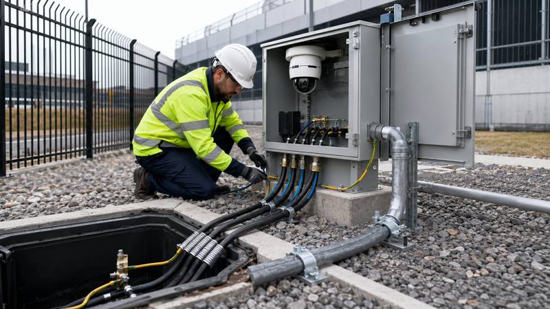
- UV and temperature extremes
- Rain, condensation and humidity
- Rodents and insects
- Oil and chemicals
- Direct burial or underground ducts
- Lightning and surge events
- Vibration and mechanical damage
- Long pulling routes
Specify outdoor-rated or indoor/outdoor cable, water blocking, armour, UV resistance, jacket material, operating temperature, bend radius and pulling tension. Use properly designed surge protection and grounding. Fibre is often preferred between buildings because it provides electrical isolation, but metallic armour and strength members still require an engineered bonding approach.
9. Submittal, BOM and Commissioning
Access-Control Cable Submittal
An access control cable submittal should make the offered construction traceable to the drawings, schedules and specification. Include:
- Security riser, bus topology, door schedule and camera schedule
- Cable schedule with manufacturer, exact part number and intended circuit
- Conductor, pair, impedance, resistance, capacitance, shield, drain and jacket data
- Fire, CPR/LSZH, plenum/risers, outdoor, UV, water-blocking and temperature evidence as applicable
- OSDP, ONVIF and equipment-compatibility evidence for the exact products where required
- Lock voltage-drop calculations, PoE and switch-port budgets, and fibre-count/loss budgets
- Pathway, separation, bonding, firestopping and penetration details
- Clause-by-clause compliance statement, deviations, samples, test plan and warranty
Data-Center Security Cable BOM
Build the data center security cable BOM by system, zone and route so purchasing quantities remain traceable to the design.
| BOM field | Required content | Procurement purpose |
|---|---|---|
| Identity and use | Item code, system, zone, circuit/device use, origin and destination. | Links every quantity to a drawing and schedule. |
| Cable definition | Pair/conductor count, size, shield, jacket, fire/environmental rating, manufacturer and part number. | Prevents a generic description from replacing the approved construction. |
| Quantity | Route length, number of runs, total length, wastage allowance, drum/reel length and spare capacity. | Supports realistic ordering, pulling and stock control. |
| Accessories | Connectors, patch panels, ODFs, glands, joints, closures, labels, firestopping and mounting hardware. | Avoids an incomplete cable-only order. |
| Approval | Data-sheet reference, compliance evidence, approved equal status, deviation and remarks. | Preserves technical approval through purchasing and delivery. |
Commissioning
- Verify door operation under normal, fire and power-loss states
- Confirm OSDP Secure Channel, addressing, termination and unique key handling
- Test reader communication, supervision and tamper reporting
- Measure lock voltage at worst-case load
- Certify copper channels and test PoE at maximum device load
- Inspect camera image, frame rate, latency, recording and analytics
- Test fibre loss, polarity, failover and diverse routes
- Save as-built routes, labels, addressing, test results and configuration backups
Common Planning Errors
- Using one generic “access-control cable” for reader, lock and monitoring circuits
- Installing OSDP devices but leaving Secure Channel disabled
- Ignoring lock voltage drop and inrush current
- Treating camera wattage as the complete PoE budget
- Using copper between buildings without surge and grounding analysis
- Selecting category cable without checking conductor material or PoE temperature
- Trusting an ONVIF logo without verifying the exact registered product
- Putting all critical security links in one pathway
- Omitting spare fibres, switch ports and rack capacity
- Failing to coordinate locks with fire alarm and egress requirements
How ZION Can Support the Campus
ZION can coordinate access-control, RS-485, security, CCTV coaxial, Cat6/Cat6A, indoor/outdoor fibre, armoured cable, ODF, patch panels, closures, patch cords and related connectivity against one approved campus schedule. Product-specific OSDP suitability, CPR class, fire performance, outdoor rating and third-party approvals must be confirmed for the exact offered item.
Related ZION Resources
Use this ZION resource when the project needs a matching product family or supporting cable selection context.
Use this ZION resource when the project needs a matching product family or supporting cable selection context.
Use this ZION resource when the project needs a matching product family or supporting cable selection context.
Use this ZION resource when the project needs a matching product family or supporting cable selection context.
Frequently Asked Questions
What cable is needed for OSDP readers?
An OSDP reader cable normally uses a balanced twisted pair suitable for the controller's RS-485 interface, plus the conductors needed for reader power. Specify characteristic impedance, conductor resistance and size, shield and drain requirements, fire and environmental rating, segment length, topology, termination, and the reader/controller manufacturer's limits. Do not select it by the OSDP label alone.
What is the difference between Wiegand and OSDP cabling?
Wiegand cable is usually a dedicated point-to-point, multi-conductor run from each reader to its controller. OSDP uses a two-wire RS-485 data channel and can support addressed devices on an approved bus. Wiegand vs OSDP cabling therefore differs in conductor arrangement, topology, termination, distance planning and commissioning; OSDP Secure Channel also adds authenticated encryption but must be enabled and managed in the system.
Can RS485 cable be used for OSDP?
Yes, an RS485 cable for OSDP can be used when its electrical construction, impedance, capacitance, conductor size, shielding, jacket rating and permitted length meet the exact reader and controller requirements. RS-485 compatibility does not by itself confirm OSDP interoperability or Secure Channel configuration.
Can access-control cable and CCTV cable share a pathway?
They may share an access control CCTV pathway only when the adopted code, project specification, pathway fill, segregation, firestopping, EMC and maintenance rules permit it. Keep circuit identification and containment organized, maintain required separation from power, and use physically diverse routes where a common pathway would create an unacceptable single point of failure.
What cable is needed for data-center CCTV and access control?
A data center security cable schedule typically combines OSDP or Wiegand reader cable, correctly sized lock-power and monitoring conductors, solid-copper Cat6 or Cat6A for suitable IP-camera channels, and optical fibre for campus backbones, long distances, EMI exposure or electrical isolation. Outdoor areas may also require UV-resistant, water-blocked, armoured or indoor/outdoor constructions.
How should security cabling be separated from power circuits?
Security cable separation must follow the locally adopted electrical and fire codes, the project specification and equipment instructions. Use dedicated low-voltage containment where required, observe the prescribed spacing from mains and high-current circuits, cross power at approximately 90 degrees when separation cannot be maintained, and use approved barriers, bonding and firestopping. The designer or AHJ should approve the project-specific distance.
What should an access-control cable submittal include?
An access control cable submittal should include the cable schedule and part numbers, conductor and pair construction, electrical data, shield and jacket details, fire and environmental ratings, manufacturer data sheets, compliance evidence, door and topology schedules, voltage-drop calculations, pathway details, test requirements, samples where requested, and a clear comparison with every specification clause.
How should a data-center security cable BOM be structured?
Structure the BOM by system, zone, route and cable type. Give each line a unique item code, device or circuit use, endpoints, cable construction and rating, estimated route length, quantity, wastage allowance, drum or reel plan, accessories, approved manufacturer and part number, compliance evidence, and remarks for alternates or installation constraints. Keep active equipment and installation accessories on linked but distinguishable lines.



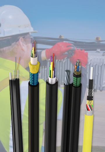 Fiber Optic Cable
 Fiber Optic Tools
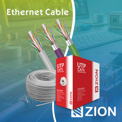 Ethernet Cable
 Coaxial Cable
 Fire & Security Cable
 Voice, Audio & Video
 Power & Control Cable