5G networks may use low-band, mid-band or high-band spectrum to support wide-area coverage, capacity growth or hotspot access. Regardless of the band, every new site or capacity expansion still requires the correct fiber connections, RF jumpers, DC power conductors, grounding parts, sealing materials and labeling accessories.
The International Telecommunication Union notes that low-band spectrum such as 600, 700 and 800 MHz can help provide rural broadband and broader coverage. Mid-band spectrum often balances coverage and capacity, while high-band spectrum is better suited to high-capacity hotspot areas. Some countries have assigned 600 MHz for mobile networks, while other markets use 700, 800 or 900 MHz more commonly. However, the accessory package should still be based on equipment interfaces and site design, not inferred from country or band alone.
What Is a 5G Site Ancillary Kit?
A site ancillary kit is a controlled set of passive connection and installation materials used to connect, protect, identify and maintain active radio equipment. Depending on the site design, the kit may include outdoor single-mode fiber jumpers, 50 Ω low PIM RF cable assemblies, −48 V DC power leads, grounding conductors, compact fiber distribution boxes, cable glands, conduit, heat-shrink materials, sealing products, cable clamps, labels, cleaning tools and maintenance spares.

A kit does not mean one universal product set for every 5G base station. It means approved materials are grouped and packaged according to a defined site type, work order or radio equipment configuration. A well-controlled kit reduces scattered purchasing while preserving engineering control over the technical design.
Why Low-Band and Multi-Band Sites Need More Accessory Planning
Low-band spectrum can extend the economic coverage area of mobile sites, while mid-band and high-band deployments often increase the density of rooftop sites, small cells and high-capacity nodes. Network construction may therefore include rural towers, roadside facilities, suburban sites, rooftop installations and dense urban capacity points, each with different environmental and logistics conditions.
Many 5G sites are also multi-band deployments. Low-band coverage equipment may be co-located with mid-band capacity equipment, existing systems or independent antenna configurations. That increases the number of physical interfaces and raises the cost of small BOM mistakes.
A wrong connector, cable length, gland, lug or sealing part may prevent installation even when radios, antennas and baseband equipment are already on site.
RF assemblies affect insertion loss, return loss and passive intermodulation; fiber assemblies affect insertion loss, return loss and end-face contamination risk.
Transport, tower crews, permits, service interruption and repeated climbs often cost more than the jumper or connector itself.
A better commercial unit is a tested, traceable and installable connection path, not simply a loose cable.
Start with the Interface Table, Not the Product Catalog
Before selecting products, convert the approved site design into an interface table. Each row should record the start and end point of a connection path. Approved installation documents from radio and antenna manufacturers remain the controlling reference, and accessory suppliers should not infer interface types from frequency band alone.

| Connection path | Information to confirm |
|---|---|
| Baseband or distribution point to radio unit | Fiber type, fiber count, connectors at both ends, polarity, route length, protection and pulling method |
| DC distribution to radio unit | System voltage, maximum current, route length, allowed voltage drop, conductor size, terminal type, polarity and protective device |
| Radio unit to antenna or RF passive component | Frequency range, impedance, connector series and gender at both ends, cable diameter, length, loss limit, VSWR or return loss, and PIM requirement |
| Radio unit or antenna to RET/AISG equipment | Interface version, connector, cascade arrangement and approved equipment configuration |
| Equipment to grounding system | Conductor material and cross-section, lug hole size, grounding point, routing path and corrosion protection method |
| Outdoor cable entry | Opening or gland size, cable outer diameter, sealing method, bend radius and target ingress protection rating |
Outdoor OS2 Fiber Jumpers for Fronthaul and Site Interconnection
OS2 single-mode fiber assemblies provide long transmission distance and low attenuation, so they are widely used in outdoor communication links. However, “outdoor OS2 jumper” is not a complete specification. An RFQ should at least define simplex, duplex or multi-fiber construction; connector series and keying at both ends; UPC or APC end-face where applicable; installed length and tolerance; cable outer diameter; minimum bend radius; UV-resistant outdoor jacket; crush, tensile, repeated bending and temperature requirements; pulling eye or dust cap requirements; factory insertion loss and return loss records; end-face inspection criteria; and serial number or test report traceability.
Outdoor hardened connectors, standard LC interfaces and other equipment-side interfaces are not interchangeable. Confirm exact endpoints from the approved site BOM, equipment document or controlled mating sample. Field acceptance should not stop at continuity; it should include maximum insertion loss, minimum return loss, end-face inspection, polarity where required, and performance after agreed environmental or mechanical tests.
50 Ω Low PIM RF Jumpers
RF jumpers may connect radio units to antennas, combiners, filters or other RF passive devices. Their specification must come from the actual RF link. At minimum, the RFQ should include operating frequency range, 50 Ω impedance, connector series and gender at both ends, jumper length and tolerance, cable construction and diameter, maximum insertion loss at specified frequencies, return loss or VSWR requirement, and the PIM test method, frequency point, power level and acceptance limit.

4.3-10, 7/16 DIN and N-type connectors may appear in mobile infrastructure, but a connector should not be selected only because it is common in the market. Check the port drawing, gender, mechanical space and approved interface requirement first. Contaminated mating surfaces, insufficient or excessive torque, damaged cable and poor waterproofing can all degrade an assembly that tested correctly at the factory.
−48 V DC Power Leads, Grounding and Surge Path Accessories
Telecom radio equipment often uses a nominal −48 V DC power architecture, but conductor size cannot be selected from voltage alone. The calculation should consider maximum continuous current, route length, allowed voltage drop, ambient temperature, installation condition, bundled-cable derating, terminal temperature rating and coordination with protective devices.
Grounding is part of the equipment protection system, not a miscellaneous item. A passive accessory package may include grounding conductors, crimp lugs, bonding straps, heat-shrink tubing, anti-corrosion materials and labels. Site grounding design, equipotential bonding and surge protection should follow the approved electrical and lightning protection design. A cable kit supplier can provide specified components, documentation and test records according to those requirements.
Outdoor Sealing, Routing and Labeling
Heat, ultraviolet exposure, dust, sand particles, mechanical movement and maintenance work can all affect outdoor connections. Therefore, an ancillary kit may need correctly sized cable glands, branch boxes or distribution boxes with the required IP rating, conduit and compatible fittings, UV-resistant ties or clamps, strain-relief and bend-control parts, cold-shrink or heat-shrink sealing systems, dust caps, cleaning tools, and durable cable and port labels.
IEC 60529 defines ingress protection ratings, but an IP rating applies to the specific enclosure and assembly condition tested. Separate parts with individual ratings do not automatically make the completed field connection meet the same rating. IEC 60332, IEC 60754 and IEC 61034 address different cable fire characteristics, including flame propagation, halogen acid gas and smoke density. They should be applied when the installation area or project specification requires them.
Three Practical Kit Formats
Different site phases call for different kit formats. New-site deployment, capacity upgrade and remote-site maintenance should not simply copy the same BOM. Materials should be organized around the installation objective, outage window, inventory strategy and service restoration requirements.
For a complete and approved site configuration, including specified fiber, RF, DC power, grounding, sealing, routing and labeling materials, packed by installation area or tower height where useful.
For adding radio units, sectors or bands to an existing site, separating reusable installed materials from new components and approved interface conversion items.
For maintenance at difficult-to-access locations, usually with a limited number of pre-tested high-impact components and common consumables.
Label formats, cleaning materials, packaging rules and report formats can be standardized; equipment-side interfaces, cable lengths, terminal geometry and performance limits usually need design confirmation.
Recommended Qualification and Acceptance Process
A reliable supplier qualification process can be organized into five stages: document review, first article samples, laboratory validation, controlled field trial and production traceability. Document review should cover approved drawings, interface tables, BOMs, material data sheets, compliance paths, and inspection and test plans. First article samples help confirm dimensions, endpoint construction, labeling, packaging and installation fit before mass production.
Laboratory validation should be matched to the component type: insertion loss, return loss, polarity and end-face condition for fiber; insertion loss, VSWR or return loss, specified-condition PIM and assembly quality for RF; conductor resistance, voltage drop assumptions, continuity, temperature rise where needed, dielectric withstand and terminal pull-out for DC power. A controlled field trial then uses the planned tools and work instructions at a representative site to record installation time, routing issues, sealing quality, connector operating space and improvements required before approval.
How ZION Supports Configurable 5G Site Kits
ZION can support contractors, distributors, system integrators and maintenance service providers with configurable passive connection kits, including outdoor fiber assemblies, RF coaxial assemblies, low-voltage DC power assemblies, fiber distribution, grounding and installation accessories. A practical process starts with the customer’s approved site BOM and endpoint interface table, then separates common materials from configurable interfaces before preparing controlled drawings, compliance matrices, representative samples and test records.
For proprietary or hardened interfaces, the project should first confirm mechanical, optical or electrical requirements and complete verification through samples or controlled mating parts. Materials can then be packed by site, sector, tower height or work order, with new-site, upgrade-site and maintenance-spare configurations supporting the local inventory plan.
Recommended ZION Products for Site Ancillary Kits
The products below are practical ZION starting points for the fiber, RF cable, jumper cable, connector, DC power and grounding portions of a 5G site ancillary kit. They are not a universal BOM; connector interfaces, fiber mode, cable size, route length, environmental rating and project test requirements should still be checked against the approved site design.
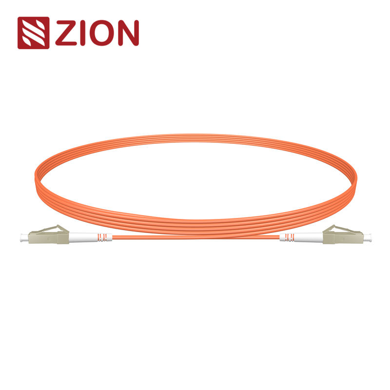
LC UPC to LC APC Simplex Fiber Patch Cord
Use as a connectorized fiber reference when the site interface table confirms LC endpoints, polish type, fiber mode, jacket and length.
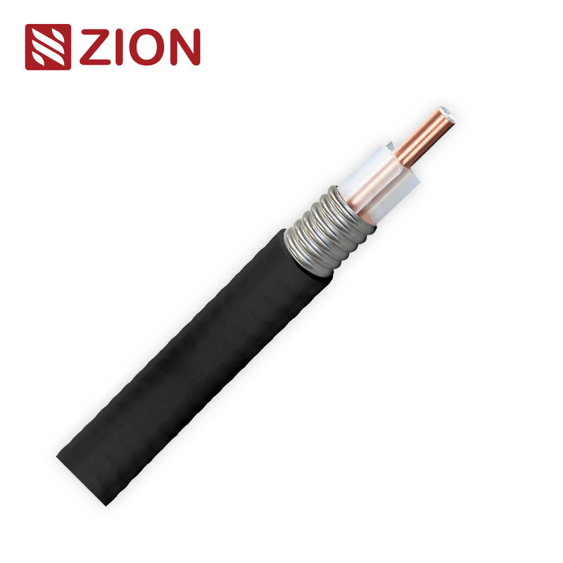
NO.7101117 1/2" Aluminum Air Dielectric RF Coaxial Cable
Use as a main RF coaxial cable candidate for feeder routes where impedance, loss, power handling, jacket and installation radius match the design.

1/2" Super Flex Jumper Cable, 4.3/10 Male to 4.3/10 Male
Use for ready-to-install RF interconnects where bend space, connector gender, frequency range, VSWR and PIM limits must be controlled before delivery.
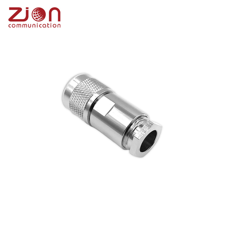
N7DMSCL N Male Clamp Straight Connector for 7D-FB Cable
Use where a 7D-FB cable path requires an N male straight clamp connector; confirm cable OD, interface standard and installation direction.
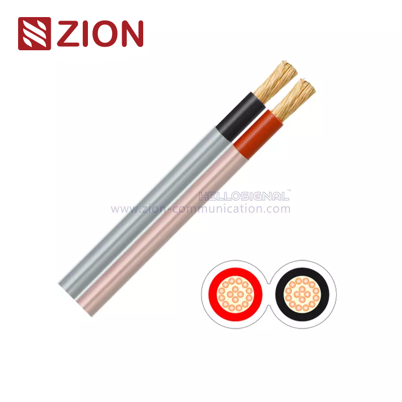
PVC Battery Cable
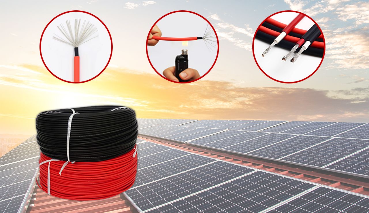
A flexible twin-core cable option for DC battery and low-voltage power connections, with conductor size selected by current, route and voltage drop.
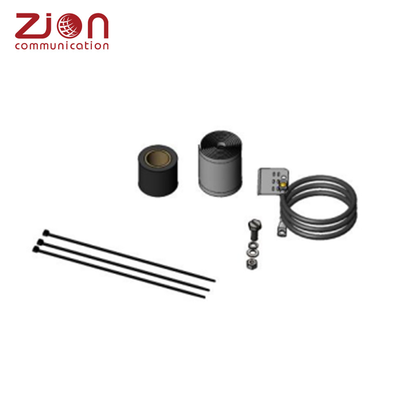
Standard Grounding Kit for 1/4"-3/8" Cable
Use for the grounding portion of coaxial cable paths where the cable diameter, lug, conductor and waterproofing requirements match the project design.
5G Site Ancillary Kit RFQ Checklist
To prepare an accurate proposal, provide the number and type of sites, whether the project is new-build, upgrade or spare support, the tower, rooftop, pole or cabinet configuration, delivery plan, local inventory requirement, approved drawings, BOM version and packaging rules.
| Category | RFQ information |
|---|---|
| Fiber assemblies | A-end and B-end connectors, fiber type and count, end-face, polarity, keying, length, jacket, route, pulling requirement, IL/RL limits and test report format |
| RF assemblies | Frequency range, RF path, connector series and gender at both ends, cable type and length, insertion loss, VSWR or return loss, PIM test condition, sealing and torque requirements |
| DC power assemblies | Nominal system voltage, maximum load current, one-way route length, allowed voltage drop, conductor size, insulation and jacket, environmental rating, terminal and lug drawings, protective device information |
| Grounding and installation accessories | Grounding conductor, lugs, cabinet and gland interfaces, sealing method, conduit, clamps, labels, consumables, project standards and destination-market compliance documents |
FAQ
Are 5G site ancillary kits completely different for each frequency band?
Not always. Frequency band affects radio equipment, antenna systems and RF paths, but fiber, DC power, grounding and installation accessories still depend on the approved equipment architecture and site design. RF components must support the actual operating frequency range and required performance limits.
Can one accessory kit fit every radio equipment brand?
Universal compatibility should not be assumed. Different equipment may use different fiber interfaces, power connectors, RF ports, keying arrangements and installation methods. Consumables can be standardized, but equipment-side assemblies must be verified.
Which RF connector should be selected for a new site?
Select the connector specified in the approved interface documentation for the radio unit, antenna or RF passive component. Market popularity is not a substitute for the approved interface requirement.
How should −48 V DC power cable size be determined for a radio unit?
Cable size should consider current, route length, allowed voltage drop, environment, installation conditions, conductor resistance, terminal ratings and protective devices. The final specification should be approved by qualified project design personnel.
Does an IP67 or IP68 part guarantee the completed field connection has the same IP rating?
No. The completed connection must use compatible components and be assembled in the configuration covered by testing or certification. Installation workmanship and sealing instructions remain essential.
What documents should be requested when qualifying a second source supplier?
Request controlled drawings, material data sheets, compliance matrices, first article test results, applicable IL/RL, PIM and electrical test reports, inspection records, traceability information and change control commitments.
Conclusion
As 5G networks expand across wide-area coverage, indoor coverage, fixed wireless access and high-capacity hotspots, site types are becoming more diverse. For the supply chain, this creates stronger demand for reliable passive connection and installation materials, but it does not mean unverified universal accessory kits are suitable.
A more reliable method is to build the kit from the approved interface table: standardize the repeatable parts, verify configurable assemblies, and package materials around the contractor’s installation workflow. Customers can provide ZION with site BOMs, endpoint interface tables or sample requirements to develop controlled ancillary kits for new sites, capacity upgrades or remote-site maintenance.
References: ITU guidance on low, mid and high bands for 5G, IEC 60794 optical fiber cable requirements and test methods overview, IEC 61300-1:2022, IEC 61753-1:2018+A1:2020, Saudi CST low-band spectrum example, and SABER HS code search.
Prepare a Configurable 5G Site Kit
Share your approved site BOM, endpoint interface table, drawings, environmental requirements, and testing expectations so ZION can help prepare a controlled accessory package for deployment or maintenance.
Request Project Support



 Fiber Optic Cable
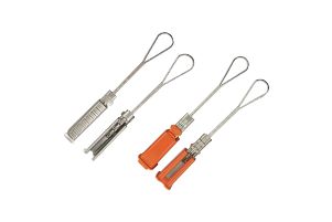 Fiber Optic Tools
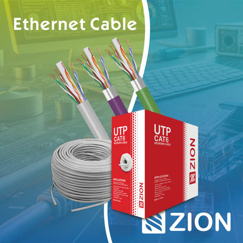 Ethernet Cable
 Coaxial Cable
 Fire & Security Cable
 Voice, Audio & Video
 Power & Control Cable