Troubleshooting: Common FTTH Installation Failures and Their Remedies
Author: Isaac Publish Time: 04-03-2025 Origin: Site
FTTH Troubleshooting: Common Failures and Fixes A symptom-based workflow for optical loss, ONT registration, IP service, speed, splitter paths, and field records.
An FTTH fault is easier to isolate when you separate the physical optical path from device registration, IP service, and the customer LAN. A red LOS indicator, a powered-off ONT, a registered ONT with no IP address, and slow Wi-Fi may feel similar to the subscriber, but they require different tests. This guide follows the symptom from the customer premises toward the OLT and avoids changing unrelated settings before the fault boundary is known.
Safety first: Never look into a fiber end or optical port. Treat disconnected fibers as potentially active. Keep glass shards controlled and use approved disposal. A visual fault locator should only be connected to a fiber that is disconnected from active equipment and confirmed safe for the test.
1. Protect Service and Capture the Symptom
Before moving a patch cord or rebooting equipment, record the ONT indicators, OLT alarms, affected subscribers, start time, recent work, and whether the fault is continuous or intermittent. Confirm the vendor-specific meaning of each LED; the same label does not always represent the same state on every ONT.
One subscriber affected: begin with local power, drop cable, connectors, ONT registration, Ethernet, and Wi-Fi.
Several subscribers on one branch affected: check the shared splitter path, distribution cable, closure, or port mapping.
Many branches affected: check the feeder, OLT port, uplink, service platform, or planned outage.
2. Build the Fault Boundary
Use the symptom to choose the first test. Do not begin with an OTDR simply because the service uses fiber.
No power indicators: investigate the outlet, power supply, cable, ONT, and local temperature.
LOS or low receive power: investigate connectors, patch cords, bends, splices, splitter path, and feeder signal.
Optical link present but ONT not registered: investigate identity, authorization, PON compatibility, OLT port, and management profile.
ONT registered but no IP service: investigate the service profile, VLAN, DHCP or PPPoE, upstream network, and customer router.
Slow service only over Wi-Fi: investigate radio coverage, interference, client capability, and router load before the optical plant.
Practical rule: prove each layer before moving upward—power, optical path, PON registration, IP service, Ethernet, then Wi-Fi and applications.
3. No Optical Signal or Low Optical Power
Likely causes
Contaminated, damaged, loose, or incorrectly seated connector.
APC/UPC mismatch, wrong adapter or patch cord, or connection to the wrong port.
Tight bend, crush, broken drop cable, high-loss splice, damaged pigtail, or closure problem.
Unexpected splitter path, excessive designed loss, failed upstream connection, or OLT transmit issue.
Recommended workflow
Verify the port and patching against the route record.
Inspect each fiber connector end face with a suitable inspection scope. Clean only with an approved method when needed, then reinspect before mating.
Check connector type, keying, seating, and the patch cord for visible stress or sharp bends.
Measure at the planned test point with a meter suitable for the PON wavelengths and live-service condition. Compare the result with the project or operator limits—not a generic internet value.
If loss remains unexplained, use an appropriate OTDR method to locate reflective or non-reflective events. Interpret the trace with launch/receive conditions and the network topology in mind.
Do not “adjust” received optical power. Find the excess-loss event or wrong path, correct it, and retest. Optical budget acceptance must use the design and operator thresholds.

4. ONT Will Not Power Up
Checks in order
Confirm the outlet or UPS works and the plug is fully seated.
Check that the adapter matches the ONT label for voltage, current capacity, polarity, and connector. Do not substitute a random adapter.
Inspect the DC lead, power button, and enclosure for damage, heat, moisture, or odor.
Disconnect nonessential Ethernet or USB devices and retry according to the vendor procedure.
If a known-good approved supply does not restore power, replace or escalate the ONT under the operator's hardware process.

5. ONT Will Not Register or LOS Remains Active
First separate optical power from authorization
A usable receive-power reading does not prove that an ONT is authorized or compatible. Confirm the actual LED state and OLT alarm, then check the ONT serial number, LOID or other operator-approved credentials, expected OLT port, and service profile.
Verify that the ONT is supported on the installed PON generation and OLT software.
Check whether the device is discovered, rejected, unauthorized, ranging, or repeatedly deregistering.
Confirm the assigned line/service profile and management configuration rather than copying settings from another subscriber.
If LOS is truly active, return to optical-path testing; if optical power is acceptable, investigate registration and compatibility.

6. ONT Is Registered but There Is No IP Service
Check the service path, not only the fiber
Confirm the correct ONT UNI port, WAN service, bridge/router mode, and operator service profile.
Verify VLAN tagging, DHCP scope or relay, PPPoE credentials, and upstream reachability according to the network design.
Check the Ethernet link rate, patch cable, customer router WAN settings, and whether another device has received the lease.
Separate DNS failure from loss of IP connectivity by checking address, gateway, and controlled reachability tests.
Review OLT, BRAS/BNG, DHCP, and authentication logs at a common timestamp when escalation is required.
Important: “Make the ONT and OLT VLAN the same” is not a universal remedy. The correct tagged, untagged, translated, or stacked VLAN behavior comes from the operator's service design.
7. Slow or Unstable Network Speed
Establish a controlled baseline
Test through wired Ethernet with a capable client and an approved local or operator test endpoint.
Confirm negotiated Ethernet speed and duplex, the customer cable category, ONT/router port capability, and device limitations.
Record throughput, latency, packet loss, time of day, and whether the condition affects one or many subscribers.
Check optical power and error counters against the operator limits, but do not assume every speed issue is optical.
Review service profile, congestion, upstream/backhaul capacity, ONT/router load, temperature, firmware, and customer traffic.
Test Wi-Fi separately for signal strength, channel use, interference, placement, band, and client capability.
Increasing the subscriber package or replacing the drop cable without evidence can hide the real cause. Repeat the same controlled test after each correction so the improvement is measurable.
8. Suspected Splitter-Path or Multi-Subscriber Failure
Treat the splitter as part of a passive path
A passive optical splitter has no software state. An apparent “partial splitter failure” can result from a contaminated connector, damaged output pigtail, wrong port map, bend, enclosure damage, poor input connection, or a damaged splitter component.
Compare the affected subscriber pattern with the physical splitter and distribution map.
Inspect the input and relevant output connections without randomly disconnecting active customers.
Compare measurements at equivalent output ports using the design split ratio and expected path loss.
Check pigtails, trays, closures, bends, moisture, labels, and recent work before replacing the splitter.
After repair, retest affected paths and update the port records.
9. Use Each Test Tool for the Right Question
Connector inspection scope
Answers whether the end face is contaminated or damaged. Inspect both sides when possible, clean when required, and reinspect before mating.
PON power meter or optical power meter
Answers how much optical power is present at a specified point. Live PON work may require wavelength-selective measurement and an instrument rated for the network. A reading becomes useful only when compared with the correct wavelength, reference, test point, and acceptance limits.
Light source and power meter / OLTS
Measures end-to-end insertion loss against a reference on an isolated test link. It does not locate the individual event causing the loss.
OTDR
Locates and characterizes events along a fiber when the wavelength, pulse width, range, launch/receive conditions, and interpretation fit the topology. Splitters and short links complicate traces. An OTDR does not by itself prove IP-service stability. ZION's FTTH drop cable testing guide provides additional acceptance-oriented context.
Visual fault locator
Helps identify continuity, macrobends, or near-end faults on suitable disconnected fibers. Never connect it into active equipment or assume visible light can pass through every PON component.

10. Close the Fault with Evidence
Record before-and-after results
Subscriber, ONT identity, OLT port, splitter/branch, and physical route.
LED state, alarms, timestamps, receive power, wavelength, instrument, and test point.
Connector inspection result, cleaning action, trace files, and corrected event location.
Registration status, service profile, IP result, Ethernet link rate, and controlled speed test.
Final repair, retest result, restored time, and any follow-up risk.
Close the ticket only after the corrected layer has passed the same controlled test that exposed the fault. Update route and port records when the physical path or assignment changes.
Frequently Asked Questions
Does a red LOS light always mean the drop cable is broken?
No. Depending on the device, it can indicate absent or insufficient optical input. Causes may include a dirty or loose connector, wrong port, tight bend, damaged splice, splitter-path fault, feeder problem, or OLT transmit issue. Confirm the device documentation and measure safely.
Can an ONT have acceptable optical power but still fail to register?
Yes. Registration also depends on compatible PON technology, device authorization, identity credentials, OLT port state, software support, and the assigned management profile.
Should every slow-speed complaint be tested with an OTDR?
No. Begin with a controlled wired test, negotiated link rate, packet loss, service profile, utilization, and optical/error data. Use an OTDR when evidence points to an unexplained physical event and the test can be performed correctly.
What is the correct optical power limit for an FTTH link?
There is no single limit for every system. The acceptable range depends on the PON class, wavelength, transceivers, split ratio, design loss, test point, and operator standard. Use the project-specific acceptance criteria.
When should a splitter be replaced?
Replace it only after measurements and inspection isolate abnormal loss or damage to the splitter rather than its connectors, pigtails, enclosure, feeder, output route, or port documentation. Retest equivalent outputs and affected subscribers after replacement.



 Fiber Optic Tools
Products 6 families
Solutions 6 markets
Resources Tools & docs
Certificate
Certification and compliance references for project review, qualification and purchasing documentation.

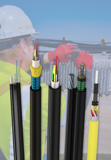 Fiber Optic CableAccess and backbone
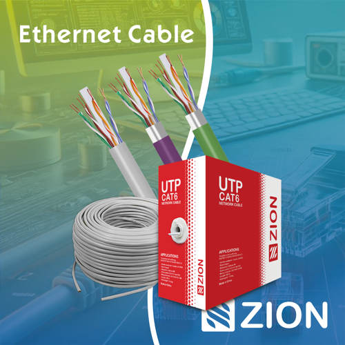 Ethernet CableCat5e to Cat8
 Coaxial CableRF and video signal
 Fire, Security & AlarmSafety systems
 Voice, Audio & VideoSignal cabling
 Power & Control CableEnergy and control
Fiber optic cable systems
Outdoor, indoor, FTTH and distribution cable lines for access networks, backbone routes and campus deployments.
 Telecom & ISP NetworksFTTH, PON, ODN
 Data Center InfrastructureServer room cabling
 Building Low-Voltage SystemsBMS, AV, weak current
 Security & Fire ProtectionAlarm, CCTV, access
 Industrial Automation CablePLC, RS485, fieldbus
 Energy & Power InfrastructureSolar, battery, power
Telecom & ISP Networks
For FTTH / PON access, outdoor fiber deployment, aerial routes, duct routes, direct burial routes, rural broadband and ODN planning.
Tools
Use calculators and planning tools for conduit capacity, PoE voltage drop and fiber optic link loss budget work.