
That transition changes the cost question. The issue is no longer simply whether fiber is the preferred long-term infrastructure. Project teams must now determine whether every route segment, cable reel, splice closure, splitter, drop package and delivery batch is aligned with the actual construction plan.
An FTTH bill of materials can be technically compliant and still be unnecessarily expensive. Excess fiber counts, poorly matched reel lengths, oversized closures, too many splitter variants, inefficient drop packaging, blanket spare ratios and badly timed deliveries all increase cost without improving network performance.
The correct objective is to reduce total installed cost. A low unit price can easily be offset by additional splices, unusable reel remnants, emergency shipments, missing accessories, idle crews or premature replacement. A coordinated BOM, by contrast, can reduce material, labor, inventory and logistics cost while preserving network performance and service life.
This guide presents eight practical ways to do that.
Start with the Right Cost Model
Before optimizing individual products, separate the project into four cost layers:
- Material cost: cables, closures, terminals, splitters, adapters, patch cords, drop assemblies, hardware and accessories.
- Installation cost: trenching, boring, pole work, pulling, splicing, testing and customer activation.
- Logistics and inventory cost: freight, warehousing, reel handling, site transfers, damage, loss and working capital.
- Lifecycle cost: fault repair, capacity additions, truck rolls, restoration time and replacement materials.
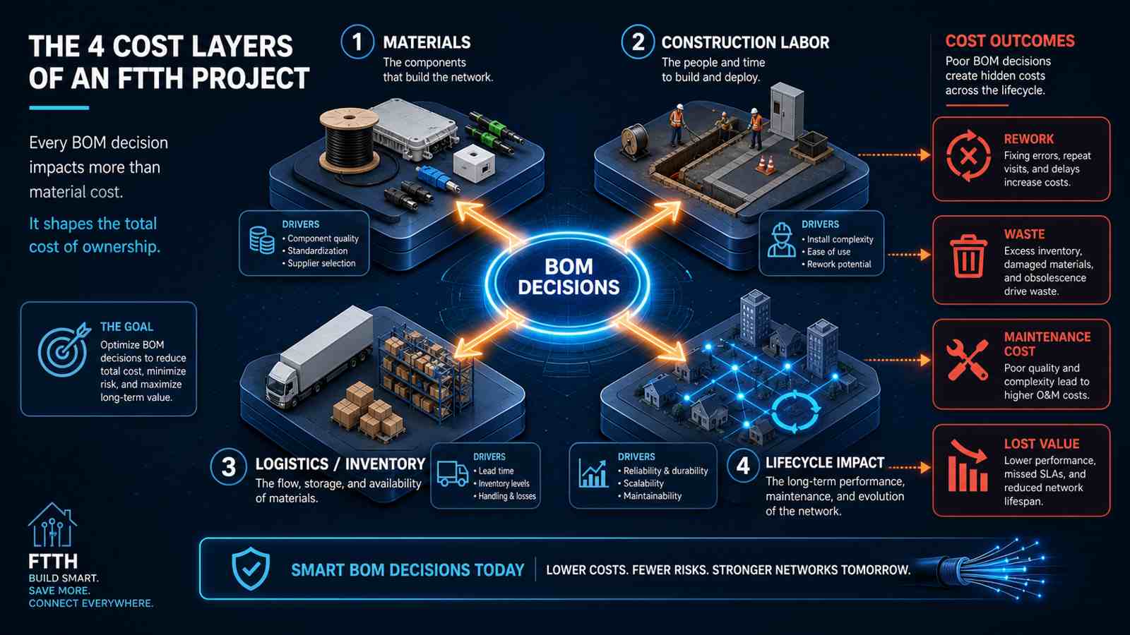
An apparent saving in one layer can increase another. For example, reducing closure capacity may lower the purchase price but cause replacement work when a service area grows. Ordering only standard reel lengths may simplify purchasing but increase field splices, scrap and labor. A useful cost review therefore evaluates total installed cost, not just the supplier quotation.
A simple starting formula is:
Total installed cost = materials + construction labor + logistics
                     + waste + rework + expected lifecycle impact
How Much Can FTTH Deployment Cost Optimization Save?
There is no responsible universal percentage. Savings depend on the starting design, aerial or underground construction, route density, local labor rates, material lead times and the maturity of the operator's existing standards.
For planning purposes, the following ranges can be used as an initial screening framework, not as guaranteed outcomes:
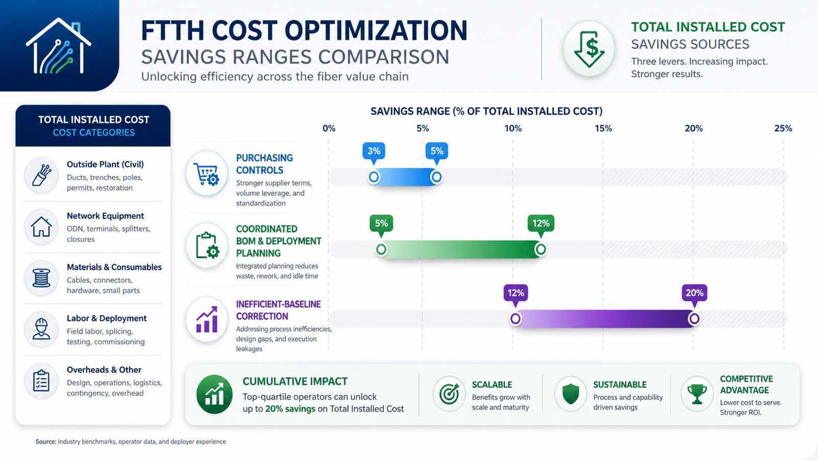
| Optimization scope | Indicative reduction in total installed cost | Typical source of savings |
|---|---|---|
| Purchasing controls only | 3%–5% | Quantity correction, packaging, spare levels and fewer emergency orders |
| Coordinated BOM and deployment planning | 5%–12% | Material optimization plus fewer splices, less waste, simpler installation and staged delivery |
| Correction of a clearly inefficient baseline | 12%–20% | Removal of overdesign, fragmented SKUs, unusable surplus, repeated field work and schedule-driven logistics |
Savings above 20% are possible only in unusual cases where the original design, BOM or construction plan contains major inefficiencies. Such a result should not be presented as a normal expectation. It usually indicates that the baseline needs redesign rather than ordinary procurement optimization.
Why material price alone has limited impact
Fiber deployment is labor intensive. As one current industry benchmark, the Fiber Broadband Association reported that labor accounted for 72% of underground and 64% of aerial deployment cost in its 2025 U.S. survey. The same study reported median construction costs of $18 per foot underground and $8 per foot aerial, with wide variation by terrain, density and construction method (Fiber Broadband Association).
These figures should not be transferred directly to another country or network. Their broader lesson is more useful: reducing the price of one cable item has a limited effect if the deployment still requires unnecessary splices, repeat site visits, emergency shipments or excessive handling.
Cost optimization creates more value when a BOM decision also removes field activity. Examples include:
- matching reel lengths to pull sections so that a joint, closure, splice cycle and test can be avoided;
- standardizing splitter and connector formats so technicians carry fewer variants and make fewer installation errors;
- packaging drops around real activation patterns so crews spend less time cutting, terminating and searching for accessories;
- coordinating cable diameters, closure ports and retention kits before materials reach the site;
- releasing materials by construction phase so quantities can be corrected using actual consumption.
A simple $1 million planning example
Consider a hypothetical FTTH deployment budget, not a benchmark for any specific network:
| Cost category | Baseline budget |
|---|---|
| Construction and installation labor | $700,000 |
| Passive network materials | $220,000 |
| Logistics, storage, waste and rework | $80,000 |
| Total | $1,000,000 |
Assume that coordinated planning achieves:
- an 8% reduction in passive-material cost through better fiber counts, closure sizing, SKU control and spare planning: $17,600;
- a 5% reduction in labor expenditure by avoiding unnecessary splices, handling and repeat work: $35,000;
- a 15% reduction in logistics, inventory, waste and rework: $12,000.
The total estimated saving is:
$17,600 + $35,000 + $12,000 = $64,600That equals approximately 6.5% of total installed cost. The example demonstrates why a coordinated review can produce more value than a narrow request for a lower cable price.
The calculations must still be rebuilt using the actual route schedule, wage rates, work methods, quantities, freight plan and approved architecture. Percentages from different optimization measures should not simply be added because several measures may remove the same underlying cost.
When Is a Formal Cost Review Necessary?
A structured review has the highest value when one or more of the following conditions apply:
- the network covers a large area or contains long feeder and distribution routes;
- underground construction, permitting or local installation labor is expensive;
- the BOM combines products from several suppliers;
- cables, closures, terminals, splitters and accessories were selected independently;
- several cable structures, connector systems or splitter formats are in use;
- custom reel lengths or preconnectorized assemblies will be ordered;
- construction will be divided into multiple zones or delivery phases;
- subscriber take rate or drop-length demand remains uncertain;
- the rollout has already experienced excess material, emergency replenishment or interface mismatches.
For a small, repeatable build using an established standard BOM, a full optimization study may not be economical. A focused check of reel lengths, interface compatibility, kit completeness, spare quantities and delivery dates may be enough.
The decision rule
Optimization is justified when the expected avoidable cost is greater than the engineering, coordination and change-control effort required to remove it. The earlier the review occurs, the better: changes made before purchase orders and production releases are normally much less expensive than corrections made after materials arrive on site.
The quality boundary remains firm. Cost reduction must not weaken optical performance, mechanical protection, water blocking, flame or environmental ratings, closure sealing, connector quality, restoration stock, realistic growth capacity or applicable standards. The objective is to remove cost that does not improve the network, not to transfer risk from the BOM into construction or operations.
1. Optimize Fiber Count by Network Segment
The common mistake
Many projects apply one conservative fiber count across long portions of the network. This can overbuild low-density distribution routes. The opposite mistake, choosing the minimum fiber count everywhere, can leave no practical capacity for growth, restoration or future services.
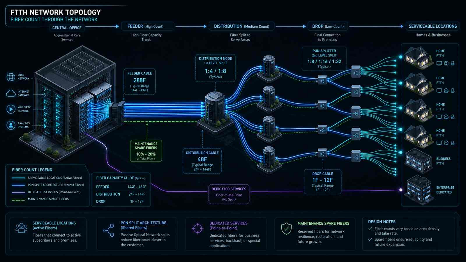
Fiber count should be calculated separately for feeder, distribution and drop segments.
What to review
For each route segment, document:
- serviceable locations passed;
- expected take rate at launch;
- take-rate forecast for the design horizon;
- PON split architecture and split ratio;
- dedicated fibers required for business, mobile, utility or community-anchor services;
- spare fibers for maintenance and route restoration;
- planned future cabinet, terminal or branch points;
- cable-count increments that are commercially and operationally practical.
A useful planning expression is:
Required segment fibers = subscriber demand after splitting
                        + dedicated-service fibers
                        + operational spares
                        + defined expansion allowance
The expansion allowance should be based on a stated scenario, not an arbitrary percentage. A feeder serving a growing town, for example, may justify more reserve than a dead-end distribution branch with a stable location count.
How this reduces cost
Segment-based optimization can reduce:
- unnecessary fiber and cable diameter;
- oversized ducts and fittings;
- reel weight and handling requirements;
- closure, tray and cabinet capacity that was added only to match an oversized cable;
- future upgrade expense where additional capacity is genuinely needed.
What not to cut
Operational spare fibers, planned business-service capacity and realistic growth allowance should remain consistent with the approved network architecture and resilience plan.
2. Plan Reel Lengths Around the Construction Schedule
The common mistake
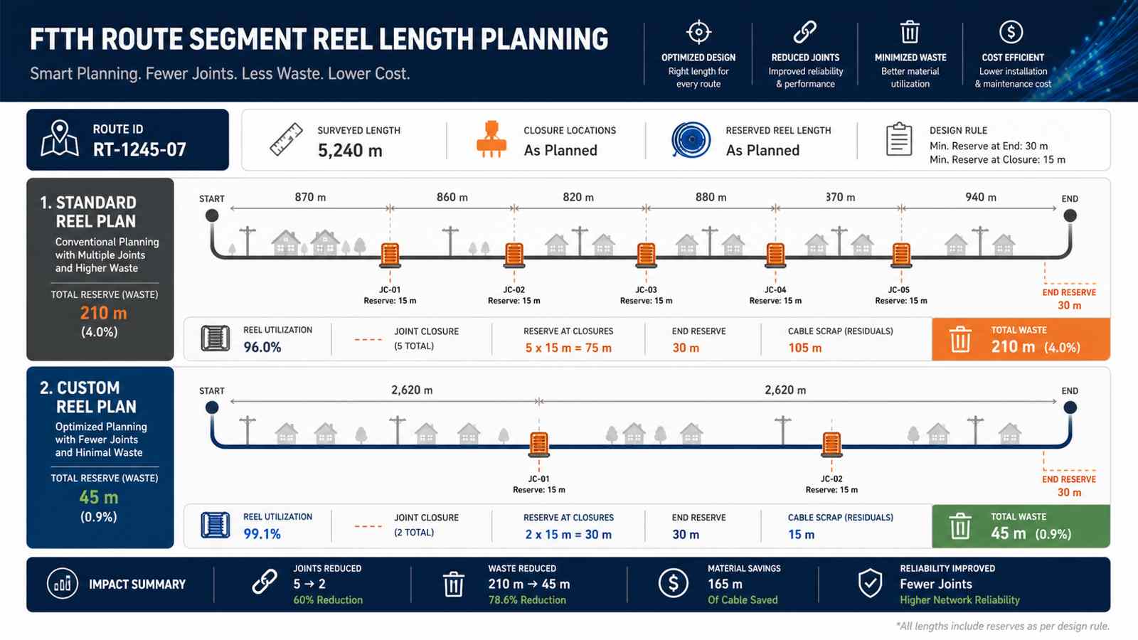
Procurement teams frequently order a standard reel length before the final route segmentation and pulling plan are complete. Crews then discover that reels are too short for a pull section, too long for site handling, or poorly matched to closure locations.
The result can be additional splices, leftover cable that cannot be reused, reel transfers between sites and emergency replacement orders.
Build a segment-to-reel schedule
Each planned cable section should include:
- route ID and installation method;
- surveyed route length;
- vertical transitions and building or cabinet entry length;
- slack at closures, poles, handholes and cabinets;
- pulling or blowing allowance;
- approved construction reserve;
- maximum reel dimensions and weight;
- drum sequence and delivery destination.
Use the following calculation as a planning framework:
Ordered reel length = surveyed route length
                    + route and elevation allowance
                    + closure and maintenance slack
                    + controlled installation allowance
The allowance must be defined by engineering and construction practice. It should not become an undocumented percentage added independently by the designer, contractor and buyer, because stacked allowances create hidden over-ordering.
Compare options before issuing the PO
For every long route, compare at least three scenarios:
- standard reels with more planned joints;
- customized reels aligned to pull sections;
- a mixed plan using standard reels where reusable and custom reels where splice avoidance creates a clear benefit.
The comparison should include cable price, reel and freight impact, number of closures, splice labor, testing time, optical-loss contribution and expected residual cable.
What not to cut
Reel lengths must remain within site lifting limits, safe transport dimensions, pulling tension, blowing distance and installation-equipment capacity. Fewer reels are not automatically better if they create field risk.
3. Separate Feeder, Distribution and Drop Specifications
The common mistake
A single cable construction is sometimes used across different route environments to simplify the tender. This may reduce the number of line items, but it can also place an unnecessarily expensive structure in benign sections, or an inadequate structure in demanding ones.
Match the construction to the route
Create a route-condition matrix before final cable selection:
| Network section | Questions to resolve | Typical specification drivers |
|---|---|---|
| Feeder | Duct, aerial or direct buried? Long pull? High fiber count? | Tensile strength, crush resistance, water blocking, cable diameter, sheath and armor |
| Distribution | Frequent branching? Limited duct space? Pole loading? | Mid-span access, compact diameter, branch handling and closure compatibility |
| Drop | Indoor/outdoor transition? Aerial span? Duct push/pull? Connectorized? | Bend resistance, flame rating, strength members, UV resistance and termination method |
Corning notes that centralized, distributed, home-run and other FTTH architectures create different tradeoffs in engineering, inventory, maintenance, restoration and expandability (Corning FTTH architecture guide). The passive BOM should follow the selected architecture rather than being standardized independently of it.
How this reduces cost
- premium armor or strength is used only where the route requires it;
- smaller distribution cable can reduce duct congestion and handling effort;
- appropriate mid-span or branch access can reduce unnecessary fiber cutting;
- drop construction is matched to installation labor and local premises conditions;
- associated clamps, glands and closures are selected once, correctly.
What not to cut
Cable structure must still meet the mechanical, environmental, fire and installation requirements for its route. Lower material cost does not justify using an indoor-only sheath outdoors, removing water blocking from a wet pathway, or using a cable that cannot withstand the planned pulling load.
4. Size Closures for Real Splice and Branching Requirements
The common mistake
Closure selection is often reduced to a headline fiber capacity. Yet two closures with the same nominal capacity may differ significantly in cable-entry configuration, mid-span capability, tray arrangement, splitter accommodation, sealing method and practical technician access.
Oversizing every closure raises material and installation cost. Undersizing can be worse: it may require external slack storage, overcrowded trays, additional closures or complete replacement during expansion.
Use a closure schedule, not a single generic SKU
For each closure location, record:
- through cable and branch cable diameters;
- number and type of cable entries;
- fibers entering, passing through, branching and being stored;
- current and future splice count;
- splice-tray capacity and organization;
- splitter or connector requirement;
- aerial, pole, pedestal, handhole or direct-buried environment;
- re-entry frequency;
- sealing and protection requirements;
- installation hardware.
Calculate practical capacity
Do not size a closure by multiplying tray count by nominal splices alone. Reserve space for fiber routing, expressed buffer tubes, uncut loop storage, splitter modules where applicable and safe future re-entry.
Use three closure tiers if the route supports them:
- trunk/feeder closure for high-count through and branch splicing;
- distribution closure or terminal for repeated service-area branching;
- compact access terminal for final customer drops.
This keeps high-capacity hardware at the nodes that need it instead of distributing the same expensive enclosure everywhere.
What not to cut
Environmental sealing, mechanical protection, bend control, cable retention and accessible fiber management are reliability requirements. Closure cost should be reduced through correct sizing and standardization, not by compromising protection.
5. Standardize Splitters Without Ignoring the Optical Budget
The common mistake
Project BOMs often accumulate too many splitter variants: several split ratios, bare-fiber and module types, multiple connector formats, different pigtail lengths and both centralized and cascaded arrangements. This increases SKU count, stocking errors, field confusion and stranded spare inventory.
Establish a controlled splitter family
Standardize, where the network design allows:
- primary split ratios;
- single-stage or cascaded topology;
- module, cassette, tray or box format;
- connector type and polish;
- pigtail length and fiber type;
- labeling and port numbering;
- inspection, test and acceptance documentation.
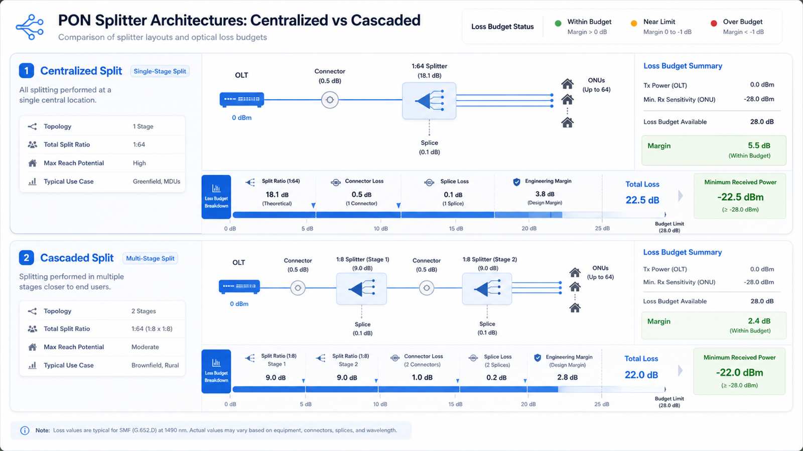
Centralized splitting uses a single splitter stage at a hub, while cascaded designs distribute splitting across more than one location. Each has implications for fiber use, field access, inventory and future changes (CommScope centralized split overview, CommScope cascaded star overview).
Verify the complete loss budget
Every standardized option must be tested against the project optical budget:
Total ODN loss = fiber attenuation
               + splitter insertion loss
               + connector loss
               + splice loss
               + engineering margin
The goal is not to force one split ratio onto every service area. It is to define the smallest approved family that covers the project while preserving received-power margin.
How this reduces cost
- fewer SKUs and fewer purchasing errors;
- simpler technician training;
- more interchangeable field spares;
- easier cabinet and tray integration;
- less inventory trapped in low-use configurations.
What not to cut
The split ratio should remain aligned with loss budget, reach, service policy and upgrade plan. Higher split ratios can reduce feeder fibers or active ports, but they must still pass received-power margin requirements.
6. Match Drop-Cable Packaging to the Activation Model
The common mistake
The drop segment is repeated at every connected location, so small inefficiencies multiply quickly. Generic bulk packaging, poorly selected pre-terminated lengths or too many uncommon drop variants can create scrap, field termination labor, damaged connectors and slow installations.
Choose the operating model first
Decide whether the project will primarily use:
- bulk drop cable cut and terminated in the field;
- pre-terminated drop assemblies in fixed length bands;
- pushable or pullable preconnectorized cable;
- aerial self-supporting drop;
- indoor/outdoor transition assemblies;
- a hybrid model for different premises types.
Then use survey or pilot data to create a drop-length histogram. Rather than ordering equal quantities of every length, concentrate inventory around the actual demand bands and keep limited stock for unusually short or long connections.
Include the complete activation kit
Packaging should be planned around what one crew needs for one installation:
- cable or pre-terminated assembly;
- compatible clamp or pulling accessory;
- customer termination box or outlet;
- adapter and patch cord where required;
- labels, protective caps and installation instructions;
- test and traceability information.
The cheapest drop cable can become expensive if technicians must return for a missing clamp, incompatible connector or additional protection component.
What not to cut
Preserve fiber bend performance, tensile and crush requirements, outdoor UV and moisture resistance, applicable indoor flame rating, connector cleanliness and factory-test requirements.
7. Set Spare Ratios by Failure Mode, Not One Blanket Percentage
The common mistake
A project may apply the same 5%, 10% or 15% spare ratio to every BOM line. This is simple but rarely economical. Cable, closures, splitters, patch cords and small accessories have different lead times, failure exposure, unit values and replacement patterns.
Create a risk-based spare model
Score each item using:
- probability of installation damage;
- frequency of field consumption;
- criticality to restoring service;
- supplier lead time;
- minimum order quantity;
- storage life and storage conditions;
- interchangeability across the network;
- geographic distance from the nearest stock point.
A practical formula is:
Planned spare quantity = installation contingency
                       + restoration stock
                       + lead-time coverage
                       - reusable surplus already available
For example, inexpensive standardized adapters and patch cords may justify a higher percentage because they are frequently handled. Large custom cable reels may require route-specific restoration lengths rather than a percentage of total purchased kilometers. Closures may be stocked by standardized capacity tier instead of project quantity alone.
Separate three types of surplus
Track these separately:
- planned installation allowance built into the working quantity;
- commissioning spare stock retained during construction;
- long-term restoration inventory transferred to operations.
Without this separation, the same contingency may be counted more than once.
What not to cut
Aggressive spare reduction can create unacceptable restoration risk when a component has a long replacement lead time, is essential to service restoration or has no approved substitute.
8. Use Staged Delivery Linked to Construction Milestones
The common mistake
Ordering the entire BOM in one shipment may appear to secure supply, but it can create months of storage, multiple site transfers, weather exposure, damage, loss, inventory-control problems and early cash outflow. At the other extreme, just-in-time delivery without schedule protection can leave crews waiting.
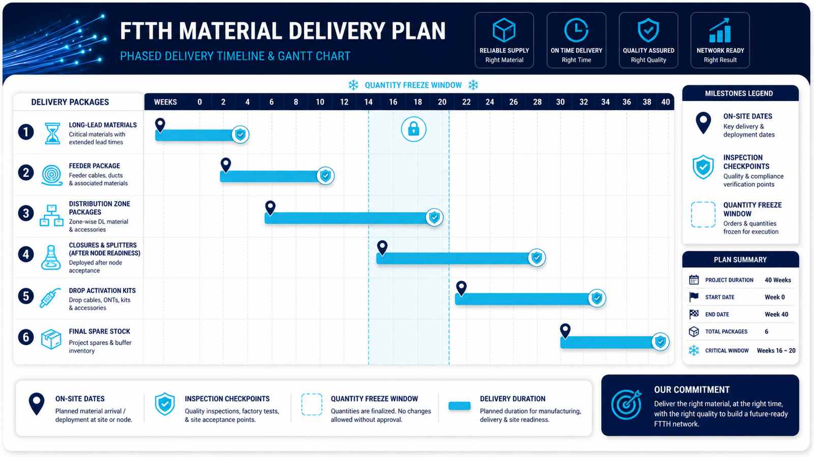
Build a phased material-release plan
Divide the project into controlled delivery packages, such as:
- long-lead and approved backbone materials;
- feeder construction package;
- distribution package by geographic zone;
- closures, terminals and splitter modules aligned to node readiness;
- drop and activation kits aligned to subscriber connection forecasts;
- final spare and restoration package.
Every batch should have:
- a bill of material by route or work package;
- required-on-site date;
- inspection and document-approval milestone;
- packaging and reel identification requirements;
- delivery location and receiving owner;
- tolerance for schedule movement;
- change-control rule for quantity revisions.
Use a freeze window
Define the date after which reel lengths, connector formats, closure configurations and labeling cannot change without commercial and schedule review. This prevents late engineering changes from silently turning finished materials into unusable inventory.
How this reduces cost
- lower storage and handling exposure;
- improved working-capital timing;
- fewer materials delivered to the wrong construction zone;
- easier inspection and traceability;
- opportunity to correct later quantities using actual field consumption from early phases.
What not to cut
Staged delivery must include manufacturing and transport buffers. It should reduce idle inventory without transferring all schedule risk to the construction crews.
A Practical FTTH Cost-Review Checklist
Before releasing the final BOM, the project team should be able to answer the following questions.
Network and route
- Are passed locations, planned connections and take-rate assumptions recorded separately?
- Is every feeder, distribution and drop segment linked to an installation environment?
- Are growth and operational spare fibers supported by an explicit assumption?
- Are closure and terminal locations reflected in the reel plan?
Cable and reels
- Does every reel have an intended route or work package?
- Were slack and installation allowances added once rather than by multiple teams?
- Are reel dimensions, weight and sequence compatible with the site?
- Can expected remnants be reassigned to another documented segment?
Closures and splitters
- Does closure capacity include through fibers, branches, trays, storage and future access?
- Are cable-entry sizes and sealing kits compatible with every cable?
- Has the splitter family been reduced to approved repeatable configurations?
- Has each split configuration passed the full ODN loss-budget calculation?
Drops and spares
- Is drop packaging based on the activation method and real length distribution?
- Are accessories included at the correct kit level?
- Are installation, commissioning and restoration spares separated?
- Does each spare ratio have a failure, lead-time or service-restoration reason?
Delivery and control
- Is the BOM divided into construction packages with required-on-site dates?
- Is there a specification and quantity freeze window?
- Can reels, cartons, closures and splitter batches be traced to inspection records?
- Is there a process for reconciling forecast quantity with actual field consumption?
FTTH BOM Planning Support for Confirmed Project Scopes
After the project owner defines the approved architecture, route conditions and applicable compliance boundary, ZION can help translate that engineering information into a coordinated passive-network material package. The purpose is to make the BOM easier to purchase, assemble, inspect and deliver by phase.
For FTTH projects with confirmed network design requirements, ZION can support the following work.
1. Structured BOM review
ZION can help organize passive ODN requirements across:
- outdoor feeder and distribution fiber-optic cable;
- aerial, duct and direct-buried structures;
- FTTH drop cable and pre-terminated drop assemblies;
- splice closures, fiber access terminals and terminal boxes;
- PLC splitters and compatible modules;
- adapters, pigtails and patch cords;
- related cable-entry, protection and installation accessories.
The review can identify incomplete specifications, incompatible interfaces, duplicated variants and items that need confirmation before quotation. ZION's FTTH/PON access-network solution and ODN solution overview provide a starting product map from the feeder section to the final drop.
2. Cable and reel planning support
Based on a customer-supplied route schedule, ZION can evaluate fiber count, cable structure, sheath or armor options, requested delivery lengths and packaging requirements. Custom reel planning can then be compared with standard production lengths to reduce unnecessary joints and unusable leftovers while respecting manufacturing, transport and site-handling limits.
3. Closure, splitter and cable-interface matching
ZION can review whether cable diameter, entry ports, splice-tray capacity, splitter format, adapter type and drop interfaces are coordinated. This is particularly important when products from several BOM sections are selected independently.
The project owner approves architecture, optical budget, capacity and compliance. ZION's contribution is to make the specified passive components easier to purchase, assemble and verify as one coordinated package.
4. Controlled SKU standardization
Where the design permits, ZION can help consolidate repeated cable constructions, splitter packages, connector formats, terminal capacities and accessory combinations. The goal is a smaller approved SKU family with clear application boundaries, not one universal product for every route.
5. Batch production and staged delivery coordination
For phased projects, quantities can be divided by construction zone, material-release schedule or requested delivery milestone. Packaging marks, reel IDs, product labels and inspection documents can be aligned with those batches, subject to the agreed order and production plan.
6. Sample and documentation review before volume production
For customized items, a practical process may include specification confirmation, datasheet review, sample or first-article approval where appropriate, packaging confirmation and then batch production. This reduces the risk of discovering an interface or labeling issue after the full quantity has been manufactured.
Information to Send for an FTTH BOM Review
To receive a useful technical and commercial review, provide as much of the following information as possible:
| Information | Why it matters |
|---|---|
| Passed locations and planned connections | Establishes service-area demand and drop quantities |
| Feeder, distribution and drop route schedule | Separates cable and hardware requirements by network layer |
| Aerial, duct, direct-buried and indoor route lengths | Determines cable structure and accessories |
| Fiber count by segment | Supports cable and closure capacity review |
| Planned closure and terminal locations | Enables splice, entry-port and reel-length planning |
| Split architecture and split ratios | Supports splitter format and optical-budget coordination |
| Connector and polish requirements | Prevents incompatible adapters, splitters and patch cords |
| Standard or target reel lengths | Supports waste, splice and transport analysis |
| Installation method and equipment limits | Prevents impractical reel or cable selections |
| Spare policy | Separates installation contingency from restoration stock |
| Required-on-site dates | Enables batch and staged-delivery planning |
| Applicable standards and certification requirements | Defines the technical and documentation boundary |
Conclusion
FTTH cost pressure cannot be solved by reducing product quality or negotiating cable price in isolation. Construction method, labor, route conditions and logistics can dominate total cost. The passive BOM still matters because poor material planning multiplies those expensive field activities.
The strongest savings usually come from eight coordinated decisions:
- use the right fiber count for each segment;
- align reel lengths with actual pull sections;
- separate feeder, distribution and drop specifications;
- size closures around real branching and splice needs;
- standardize splitters within the optical budget;
- package drops around the activation model;
- set spare quantities by risk and lead time;
- release materials in controlled construction phases.
These measures reduce waste, rework, inventory and avoidable field labor while protecting the mechanical, optical and environmental performance of the network.
For a technical and commercial review, send ZION the preliminary BOM, route schedule, location count, split plan and installation conditions. ZION can help identify specification gaps, component-interface issues, packaging options and batch-delivery opportunities within the confirmed network design.
References
- Fiber Broadband Association - 2025 Fiber Deployment Cost Report announcement
- Corning - Choosing the Right FTTH Network Architecture
- CommScope - Centralized Split Architecture
- CommScope - Cascaded Star Architecture
- ZION - FTTH/PON Access Network Solution
- ZION - Optical Distribution Network Solution
Prepare a More Controlled FTTH BOM
Share the preliminary BOM, route schedule, split plan, installation environments, required-on-site dates and compliance boundary. ZION can review the passive-network package for specification gaps, interface matching, reel planning and staged delivery options.
Request Project Support


