
When a Shielded Cat6A Channel Fits
This configuration fits data rooms, healthcare infrastructure, AV-over-IP installations and commercial areas where cable routes are close to identified interference sources or where the project specification already requires shielded balanced cabling. Shielding selection should follow the site EMC and bonding design rather than a general assumption that metal connectivity is always better.
The F/UTP horizontal cable uses an overall foil shield, while the selected patch cord uses S/FTP construction. Different shield constructions can be used within a channel when every connecting interface is shield-compatible and the finished configuration is tested. The exact BOM, grounding path and acceptance limit therefore belong in the project record.
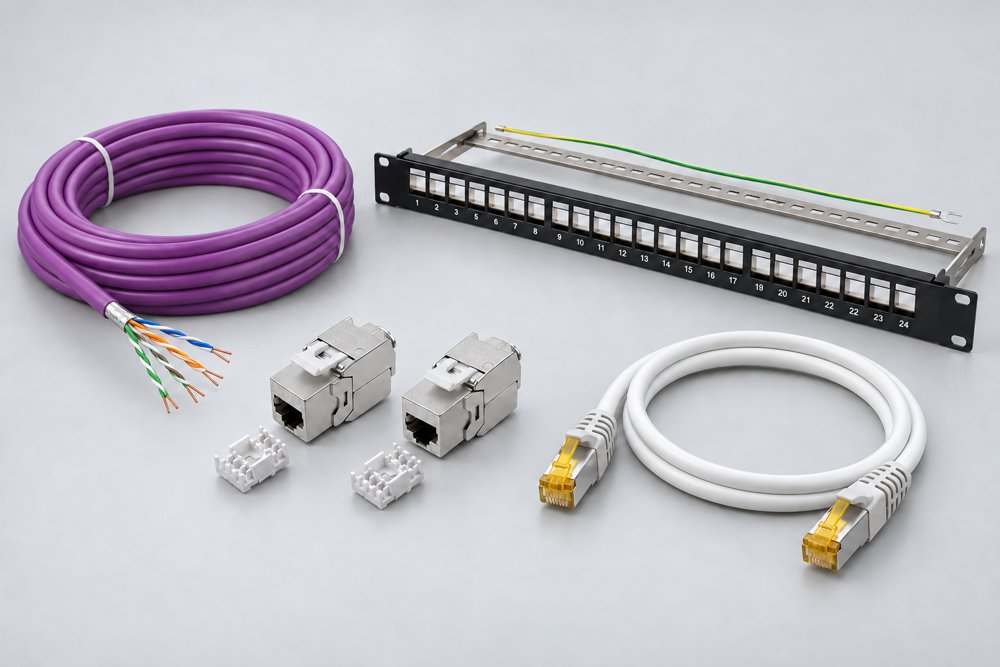
Selected Shielded Bill of Materials
The selected panel is a modular chassis rather than a fixed punch-down panel. Cat6A performance at each port is provided by the specified shielded jack, while the panel supports port organization, rear cable management and the rack bonding arrangement.
| Component | Selected model | Published specification | Role in the link |
|---|---|---|---|
| Horizontal cable | ZION 7112316 | Cat6A F/UTP, 23 AWG solid bare copper, conductor 0.57 ± 0.005 mm, LSZH, published performance through 500 MHz | Shielded permanent horizontal run |
| Shielded jack | ZCTLKJF6A-B1 | Cat6A FTP toolless jack; zinc-alloy shield; accepts 22–24 AWG solid wire; 750 RJ45 mating cycles minimum | Rack and work-area shield termination |
| Shielded panel | ZCPPF6A-1U24-KJ-B1 | 19-inch, 1U, 24-port modular shield-compatible panel; SPCC body; rear cable management | Rack-side organization and bonding interface |
| Shielded patch cord | 7241011 | Cat6A S/FTP, 28 AWG stranded copper, 500 MHz, cable OD 6.0 ± 0.2 mm, LSZH, shielded RJ45 | Switch and equipment connection |
Published Component Details
Model 7112316 uses 0.57 ± 0.005 mm solid bare copper conductors and an LSZH jacket. Its published transmission table extends through 500 MHz. For North American riser projects, ZION 7112314 F/UTP Cat6A CMR is an alternative cable construction with 23 AWG solid bare copper and a published 7.6 ± 0.2 mm cable OD.
The ZCTLKJF6A-B1 jack uses a zinc-alloy shield and accepts 22–24 AWG solid wire. Published values include 20 mΩ contact resistance, insulation resistance of ≤500 MΩ at 100 V DC, DC 1000 V / AC 700 V RMS withstand voltage for one minute, 750 RJ45 mating cycles minimum and 250 IDC cycles minimum.
| Patch-cord parameter | Published value | Design significance |
|---|---|---|
| Shielding | S/FTP | Maintains a shielded equipment interface |
| Conductor | 28 AWG, 7/0.127 mm stranded copper | Flexible high-density cord; review PoE and length requirements |
| Cable OD | 6.0 ± 0.2 mm | Check rack routing and cable-manager fill |
| Frequency | 500 MHz | Matches Cat6A component bandwidth |
| Connector | Shielded RJ45, 50 µin gold over nickel | Preserves contact and shield continuity |
Shield Continuity, Bonding and Rack Integration
The shield path begins at the horizontal cable foil and drain-wire termination, continues through the metal jack and panel, and reaches the equipment through shielded patch cords and shielded equipment ports. The panel chassis then requires a deliberate bonding connection to the rack or telecommunications bonding infrastructure defined by the project.
Prepare the cable according to the jack instruction so the foil and drain path are captured without excessive pair exposure.
Use the designated panel bonding point and verify continuity to the rack; do not rely on paint-contact or mounting screws alone.
Connect the rack to the project telecommunications bonding system using the conductor size and hardware specified by the site design.
Confirm that shielded equipment ports and cords are used where the design depends on end-to-end shield continuity.
Channel Testing and Documentation
Test the installed system with the final cable, jacks, panel and patch cords specified for delivery. Permanent-link testing verifies the fixed portion before equipment cords are added. Channel testing includes the cords that will be part of the operational link. The test limit, adapter type, link name and BOM revision should appear in the acceptance record.
For dense racks and powered endpoints, also record cable-bundle size, ambient temperature, patch-cord gauge and grounding inspection. The ZION guide on matching cable, jacks, patch panels and patch cords explains why category and shielding consistency must be reviewed as a complete system.
Frequently Asked Questions
Can an F/UTP horizontal cable be used with an S/FTP patch cord?
Yes, when the jacks, panel and equipment interfaces are shield-compatible and the finished configuration meets the required channel test. The two cable sections do not need identical shield construction.
Does a metal patch panel automatically provide grounding?
No. The panel needs a defined bonding connection to the rack or telecommunications bonding system, and continuity should be inspected and documented.
Is a shielded channel always better than UTP?
A shielded channel is appropriate when the project has an EMI-control or bonding requirement. UTP is often simpler where the environment and project specification do not require shielding.
Prepare a Shielded Cat6A BOM
Submit the cable fire rating, link length, port count, rack bonding arrangement, equipment interface, PoE load and test requirement for a component and grounding review.
Request Project Support


