Air-Blown Micro Fiber Optic Cables: Types, Structures, and Applications
Author: Site Editor Publish Time: 08-04-2025 Origin: Site
Air-blown micro fiber systems install a small optical cable or fiber unit into a pre-installed microduct by combining controlled mechanical feeding with airflow. The microduct provides a defined pathway and part of the mechanical protection, while the cable or unit is designed with suitable diameter, stiffness, mass, and surface friction for blowing.
The main decision is not simply “air-blown or conventional cable.” Project teams must choose between a lightly protected microduct fiber unit and a more robust jacketed microcable, then match its outside diameter, fiber capacity, construction, and environmental rating to the microduct and route. Installation distance and speed depend on the complete system, including duct condition, bends, pressure integrity, equipment, temperature, and installer practice.
How an Air-Blown Micro Fiber System Works
A typical system includes the optical cable or fiber unit, microduct, connectors and seals, access points, and compatible blowing equipment. The machine feeds the cable while compressed air reduces sliding contact and helps move it through the route. This differs from simply pulling a cable with a winch: the installation load is distributed along the moving cable, which can reduce concentrated tensile force when the system is correctly designed and operated.
The result is a pathway that can support phased deployment. A network owner may install a protected microduct bundle during civil works, populate only the ducts needed initially, and use spare ducts for later routes. Future expansion can avoid reopening the same trench, but only when spare, continuous, clean, correctly sized, and pressure-tight microducts remain available.
IEC 60794-5-10 addresses outdoor microduct optical fiber cables and associated microducts, while IEC 60794-5-20 covers outdoor microduct fiber units and corresponding microducts. ITU-T L.156 describes air-assisted installation methods. A project should state the required standard editions, test methods, and environmental conditions rather than treating the term “air-blown” as a complete specification.
Microduct Fiber Units vs Microduct Cables
These product groups share the same installation concept but do not provide the same level of protection. The distinction is important when a route passes through outdoor ducts, buildings, handholes, cabinets, or exposed transition points.
| Comparison | Microduct Fiber Unit | Microduct Optical Cable |
| Construction | Fibers supported by a compact resin or low-friction outer construction | One or more protected fiber tubes with strength members and an outer sheath |
| Protection level | Relies more heavily on the microduct and terminal housing | Provides more cable-level mechanical and environmental protection |
| Typical selection driver | Very small pathways, indoor drops, short branches, and low fiber counts | Outdoor access, longer routes, higher fiber counts, or demanding handling conditions |
Air-Blown Micro Fiber Cable Types
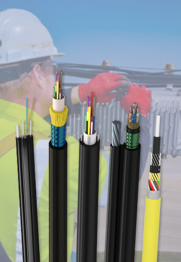
Four common construction groups cover different fiber capacities and pathway conditions. Model codes describe a product family, not a universal specification, so dimensions, fiber type, environmental rating, and blowing compatibility must be checked on the selected datasheet.

Enhanced Performance Fiber Units (EPFU)
EPFU air-blown fiber units arrange optical fibers and filler elements in a resin matrix with a low-friction, typically grooved outer layer. Their small diameter and low mass suit compact microducts, FTTH drops, building distribution, and other routes where the microduct supplies the required mechanical protection. The fiber count, bend performance, indoor material rating, microduct size, and termination method must match the project.
Uni-Tube Air-Blown Microcables
A GCYFXTY uni-tube air-blown microcable places the fibers in one loose tube, with aramid yarn reinforcement and a low-friction outer sheath. Compared with a lightly protected fiber unit, the loose tube and sheath provide additional handling and environmental protection. This structure is commonly evaluated for FTTx and access routes requiring a compact outdoor microcable.
Stranded Loose-Tube Air-Blown Microcables
GCYFY stranded loose-tube microcables use multiple fiber-bearing elements arranged around a central strength member and covered by a compact sheath. The construction offers more design flexibility for higher fiber counts and route capacity. Smaller variants may use reduced-diameter fibers or a more compact tube arrangement, but the exact fiber dimensions and compatibility should be confirmed rather than inferred from the model name.
Micro Air-Blown Fiber Units (MABFU)
MABFU products use a very compact fiber bundle supported by a resin layer and low-friction thermoplastic surface. They are considered for short distribution branches, indoor generic cabling, FTTH drops, and small microducts. Because the fiber unit depends strongly on the surrounding pathway, transition points, exposed sections, fire-performance requirements, and termination protection need explicit review.
How to Choose the Right Construction
Start with the route: record total distance, section lengths, bends, elevation changes, access chambers, indoor/outdoor transitions, and available blowing points.
Match cable and microduct: confirm cable outside diameter, microduct inside diameter, wall type, pressure rating, connector system, and the supplier's recommended fill range.
Select the protection level: use a fiber unit only where the microduct and terminal housings provide adequate lifetime protection; select a jacketed microcable when the route and handling demand more protection.
Define fiber requirements: specify fiber count and type, attenuation, bend performance, identification, spare capacity, and the splicing or connectorization plan.
Check the environment: include temperature, water exposure, chemicals, rodents, fire performance, direct-burial or duct use, and any exposed transition length.
Confirm installation evidence: request the compatible blowing equipment, pressure and airflow limits, route assumptions, lubricant guidance, crash-test setting, and demonstrated test method for the proposed cable-and-duct combination.
Installation Factors That Control Blowing Performance
Published maximum distance or speed figures are meaningful only with their test conditions. Real routes add bends, joints, contamination, leakage, temperature changes, and elevation differences. The cable's stiffness and surface design must work with the selected microduct and blowing head; more air pressure does not automatically correct a poor route and can exceed equipment or duct limits.
Before blowing, the installer should verify duct continuity and internal clearance, clean and calibrate the route, confirm pressure integrity, prepare seals and connectors, and set the machine's cable-protection or crash-test function. During installation, feed force, airflow, speed, drum behavior, and the cable end at the receiving point should be monitored. Minimum bending limits and allowable installation temperature come from the actual product data.
Removal or replacement may be possible in a suitable microduct system, but it should not be promised for every installed route. Long-term deformation, duct damage, water, dirt, tight bends, cable packing, or incompatible materials can change the result. Keep route records and test an existing duct before planning an upgrade.
Typical Applications
| Application | Common Design Direction | Selection Focus |
| FTTH drops and building distribution | EPFU or MABFU; compact uni-tube cable where more protection is needed | Small pathway, bend performance, indoor fire rating, termination protection |
| Campus and access networks | Uni-tube or compact stranded loose-tube microcable | Outdoor protection, route length, branching plan, spare ducts |
| Metropolitan and high-capacity access | Stranded loose-tube microcable | Fiber density, duct occupancy, splice plan, installation sections |
| Phased network expansion | Any compatible unit or cable selected for each pathway | Protected spare ducts, records, sealing, future access and capacity plan |
Information Needed for a Project Specification
A useful request for quotation should include:
Network application, installation environment, route drawing, section lengths, bend count, and elevation profile.
Existing or proposed microduct outside and inside diameters, material, wall type, bundle arrangement, pressure rating, and connector details.
Required fiber count, fiber standard, identification, drum or pan length, spare capacity, and termination plan.
Indoor/outdoor, temperature, water, chemical, rodent, UV, fire-performance, and transition requirements.
Applicable standards, installation test expectations, inspection documents, attenuation results, packing, and route-specific blowing validation.
Frequently Asked Questions
What is the difference between an air-blown fiber unit and a microcable?
A fiber unit has a lighter protective construction and relies more on the microduct and terminal housing. A microcable normally includes one or more protected fiber tubes, strength elements, and a jacket, giving it greater cable-level protection.
How far can an air-blown micro cable be installed?
There is no universal distance. Cable and duct dimensions, route bends, elevation, leakage, cleanliness, equipment, pressure limits, temperature, and installer settings all affect the result. Use route-specific guidance or a representative installation test.
Can a blown cable always be removed and replaced?
Replacement can be possible in a compatible, undamaged microduct route, but it is not guaranteed. Test the duct and review the cable, route history, bends, joints, water, contamination, and available pulling or blowing access before planning removal.
Which cable type is suitable for high fiber counts?
Stranded loose-tube microcables usually provide the broadest design space for higher fiber counts. The correct model still depends on duct size, route, protection level, fiber type, installation limits, and splicing plan.



 Fiber Optic Tools
Products 6 families
Solutions 6 markets
Resources Tools & docs
Certificate
Certification and compliance references for project review, qualification and purchasing documentation.

 Fiber Optic CableAccess and backbone
 Ethernet CableCat5e to Cat8
 Coaxial CableRF and video signal
 Fire, Security & AlarmSafety systems
 Voice, Audio & VideoSignal cabling
 Power & Control CableEnergy and control
Fiber optic cable systems
Outdoor, indoor, FTTH and distribution cable lines for access networks, backbone routes and campus deployments.
 Telecom & ISP NetworksFTTH, PON, ODN
 Data Center InfrastructureServer room cabling
 Building Low-Voltage SystemsBMS, AV, weak current
 Security & Fire ProtectionAlarm, CCTV, access
 Industrial Automation CablePLC, RS485, fieldbus
 Energy & Power InfrastructureSolar, battery, power
Telecom & ISP Networks
For FTTH / PON access, outdoor fiber deployment, aerial routes, duct routes, direct burial routes, rural broadband and ODN planning.
Tools
Use calculators and planning tools for conduit capacity, PoE voltage drop and fiber optic link loss budget work.