Optical Fiber Cable for Rural Networks | Best FTTH Solutions for Vast Countryside
Author: James Publish Time: 28-03-2025 Origin: Site
Rural FTTH Fiber Cable Selection for Feeder, Distribution, and Drop Networks
Plan rural fiber routes by network segment, installation method, terrain, span conditions, environmental exposure, and the maintenance resources available after deployment.
■ Why Rural FTTH Requires Route-Based Cable Selection
Rural FTTH networks often cover long routes between dispersed subscribers while relying on existing poles, ducts, or mixed infrastructure. Hills, rivers, road crossings, lightning exposure, moisture, rodents, limited access, and fewer local maintenance resources can all change the most suitable cable construction. A cable should therefore be selected for its position in the network and its actual installation environment—not simply because it is marketed as a “rural fiber cable.”
The passive network is commonly divided into feeder, distribution, and drop segments. Each segment has a different route length, fiber-count requirement, branching pattern, installation load, and repair priority. Optical design decisions such as fiber type, split ratio, wavelength, and loss budget must be coordinated with the mechanical cable design.

■ Plan the Cable by FTTH Network Segment
| Segment | Network role | Typical cable approach | Key checks |
| Feeder | Central office or headend to a distribution point | Higher-count stranded loose-tube cable selected for the aerial, duct, or buried route | Capacity, route length, pulling or span load, restoration strategy, spare fibers |
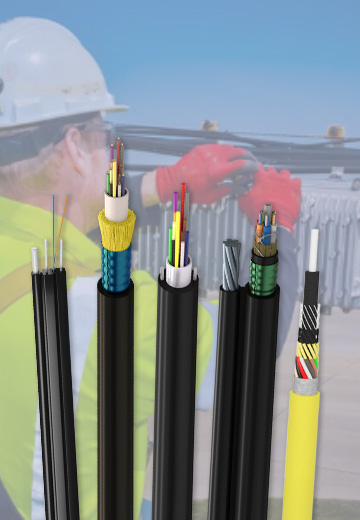
| Distribution | Distribution point to local access or branching points | Compact uni-tube, slotted-core, flat self-supporting, or figure-8 cable according to route | Branch access, pole loading, span conditions, water blocking, metallic content |
| Drop | Final connection from the access point to the subscriber | Bow-type or other purpose-designed FTTH drop cable | Indoor/outdoor transition, termination method, bend control, attachment hardware |
■ Rural Distribution Cable Construction Options
The following designs solve different route problems. Product family names describe construction, not a universal span, fire rating, rodent rating, or installation method. Confirm the exact model and current datasheet before procurement.
GYAXZY all-dielectric uni-tube cable A loose tube, aramid yarn strength layer, and LSZH sheath form a compact non-metallic construction. The current product page lists short-distance self-supporting aerial and duct installation options. Its all-dielectric construction can be useful where metallic elements are undesirable, but the required tensile design, span, hardware, and sheath test requirements must be stated for the project. |
GYGXY glass-fiber-tape uni-tube cable Glass-fiber tape surrounds the loose tube and provides a non-metallic strength and protection layer. This family can be considered for compact rural distribution routes, including selected aerial or duct installations. The current webpage contains inconsistent jacket descriptions, so the required PE, HDPE, or LSZH jacket must be confirmed on the quotation and approved datasheet. |
GTJGA slotted-core cable Tight-buffered fibers are placed in a slotted core around a steel central strength member. Water-blocking tape, laminated aluminum tape, and a PE sheath protect the core. The current product page identifies outdoor duct, non-self-supporting aerial, and vertical installation; direct burial should not be assumed without a model-specific approval. |
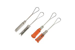
GYFXBY flat self-supporting cable A central loose tube sits between two parallel FRP rods inside a flat PE sheath. This all-dielectric structure is intended for self-supporting aerial distribution and compatible wedge clamps. Pole condition, attachment hardware, allowable span, sag, wind, ice, and clearance must be checked as part of the aerial design. |
GYAXTC8Y figure-8 steel-messenger cable This uni-tube design uses aramid yarns and a steel-wire messenger inside a figure-8 PE sheath for self-supporting aerial installation. The current product page describes short-distance aerial use. Because the cable contains steel, electrical separation, bonding practice where applicable, pole hardware, and lightning-zone design must be evaluated by the network designer. |
GYFC8A-3U multi-tube figure-8 cable Three loose tubes are stranded around a central strength member, with water-blocking yarns, laminated aluminum tape, a steel-wire messenger, and a figure-8 PE sheath. This construction supports a compact multi-tube aerial route, while the current product page still defines it as a short-distance self-supporting cable rather than a universal long-span solution. |
■ Match the Cable to the Rural Route
| Route condition | Construction direction | Do not overlook |
| Lightning-prone aerial route | Consider an all-dielectric cable such as a suitable GYAXZY or GYFXBY configuration | Span, sag, wind and ice load, clamps, pole condition, clearances |
| Short self-supporting aerial route | Flat FRP or figure-8 messenger construction according to the mechanical design | Metallic content, messenger size, attachment load, installation tension |
| Existing duct | Compact uni-tube or slotted-core construction with verified duct suitability | Duct ID, occupancy, bends, pulling length, water, cable diameter |
| Rodent exposure | Specify a product with documented rodent-resistant construction for the actual threat | Material evidence, test method, route protection, repair access |
| Indoor transition or occupied building | Use a jacket and transition method that meet the applicable installation rules | Documented flame, smoke, and halogen performance—not the LSZH label alone |
■ Installation and Maintenance Checks
Survey before design: record route length, pole spacing, elevation changes, crossings, ducts, bends, access points, and seasonal conditions.
Verify mechanical limits: compare installation tension, operating tension, crush load, minimum bend radius, and temperature with the approved product data.
Design the hardware as a system: clamps, brackets, closures, slack storage, grounding or separation measures, and pole loading must suit the selected cable.
Protect branch and splice points: place closures where technicians can reach them safely and retain sufficient slack for restoration.
Plan acceptance testing: document reel inspection, continuity, optical loss, splice results, route records, and as-built identification.
■ Information Needed for Rural FTTH Cable Selection
Prepare the following information before requesting a cable recommendation or quotation:
network segment, route map, total length, branch locations, and subscriber plan;
aerial span data, pole condition, duct dimensions, burial method, or mixed-route details;
fiber type, fiber count, spare capacity, split architecture, and optical loss budget;
wind, ice, temperature, moisture, UV, lightning, chemical, and rodent exposure;
required standards, jacket performance, drum length, packing, testing, labeling, and delivery documents.
■ Frequently Asked Questions
Which cable is suitable for a lightning-prone rural aerial route?
An all-dielectric cable can remove metallic elements from the cable construction, but the complete route still requires a span, pole, clearance, hardware, and local safety assessment. Confirm that the selected model's tensile design supports the planned spans.
Is every figure-8 cable suitable for long spans?
No. Figure-8 describes the cable arrangement, not a guaranteed span. Messenger construction, cable weight, installation tension, wind and ice load, sag, pole strength, and attachment hardware determine the allowable span.
Does an LSZH sheath prove that a cable meets every building fire requirement?
No. LSZH describes material behavior, while project acceptance depends on the specified flame, smoke, halogen, and installation requirements. Request the relevant test evidence for the exact cable model.
Can one cable type be used for feeder, distribution, and drop segments?
It may be physically possible in some projects, but it is rarely the most practical default. Fiber count, branching, termination, span or pulling load, access, and repair methods differ by segment, so each section should be specified separately.
A reliable rural FTTH design begins with the route survey and network architecture. Cable construction should then be matched to each segment's mechanical, environmental, optical, installation, and maintenance requirements.



 Fiber Optic Tools
Products 6 families
Solutions 6 markets
Resources Tools & docs
Certificate
Certification and compliance references for project review, qualification and purchasing documentation.

 Fiber Optic CableAccess and backbone
 Ethernet CableCat5e to Cat8
 Coaxial CableRF and video signal
 Fire, Security & AlarmSafety systems
 Voice, Audio & VideoSignal cabling
 Power & Control CableEnergy and control
Fiber optic cable systems
Outdoor, indoor, FTTH and distribution cable lines for access networks, backbone routes and campus deployments.
 Telecom & ISP NetworksFTTH, PON, ODN
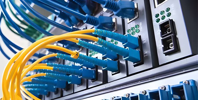 Data Center InfrastructureServer room cabling
 Building Low-Voltage SystemsBMS, AV, weak current
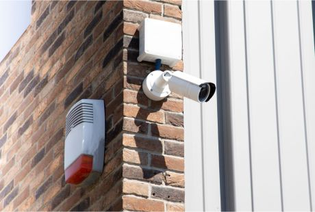 Security & Fire ProtectionAlarm, CCTV, access
 Industrial Automation CablePLC, RS485, fieldbus
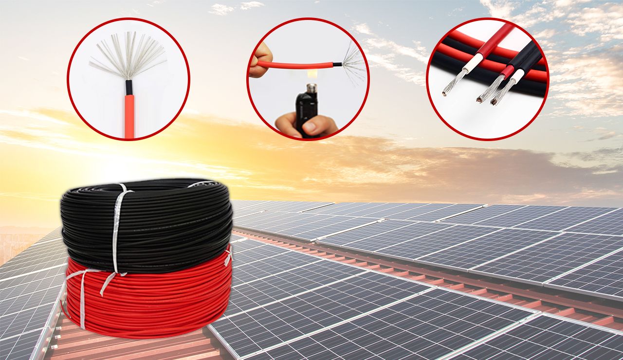 Energy & Power InfrastructureSolar, battery, power
Telecom & ISP Networks
For FTTH / PON access, outdoor fiber deployment, aerial routes, duct routes, direct burial routes, rural broadband and ODN planning.
Tools
Use calculators and planning tools for conduit capacity, PoE voltage drop and fiber optic link loss budget work.