Building Cabling Fiber Optic Cables: Indoor Network Solutions Explained
Author: James Publish Time: 10-04-2025 Origin: Site
Indoor Fiber Optic Cables for Building Cabling: Selection Guide Compare tight-buffered, duplex, bundled, branch, and micro-tube constructions for indoor network routes, termination points, and project fire requirements.
Indoor fiber optic cables distribute optical links through risers, telecommunications rooms, horizontal pathways, equipment areas, and final connection zones inside a building. The correct cable is selected by route, fiber count, termination method, mechanical support, bend space, jacket requirement, and the fire-performance rules that apply to the installation. “Indoor cable” is a broad category; it does not mean that every construction is approved for every riser, plenum, escape route, or occupied space.

■What Is Building Cabling Fiber?
Building cabling fiber is the indoor optical cable used between an entrance or distribution point and the rooms, floors, racks, panels, outlets, or equipment served by the network. In FTTx and multi-dwelling projects, it may form part of the in-building distribution and drop segment. In enterprise and data center environments, similar cable constructions can be used for backbone, horizontal, equipment, and breakout routes when the pathway and fire rating permit.
Tight-buffered fibers are convenient for direct handling and termination. Bundled or breakout constructions organize multiple fibers and add tensile support. A central strength member or parallel FRP members can improve structural control, but they also affect cable size, stiffness, branching, and the minimum bend radius. These construction choices should be matched to the installation method rather than treated as quality levels.
■Indoor Fiber Cable Types and Typical Uses
The following model families illustrate common indoor structures. Their names describe the construction, not a universal application approval. Confirm the current data sheet, available fiber options, jacket material, mechanical limits, and required test documentation before ordering.
Single-fiber tight buffer — GJJAA compact 0.9 mm tight-buffered construction can support pigtail preparation and short internal connections where the cable is adequately protected. The linked GJJA product page is currently marked unavailable, so buyers should request the current replacement instead of naming this legacy model in a new specification.

Duplex tight-buffered cable — GJFJH and GJFJBVGJFJH uses a round duplex format, while GJFJBV uses a flat duplex format. Both are intended for two-fiber links and use aramid yarn for tensile support. The flat shape may suit controlled pathways with limited profile, while the round version is often easier to route through conventional pathways. Confirm connectorization, pulling limits, and the permitted bend radius.


Multi-fiber tight-buffered bundle — GJPFJVMultiple tight-buffered fibers are grouped under a common sheath with aramid-yarn reinforcement. This structure can simplify multi-fiber indoor runs to panels or distribution points, but the exact fiber count, cable diameter, pulling load, and jacket material vary by ordered configuration.

Branch cables with a central strength member — GJBFJV-I and GJBFJVHThese multi-fiber branch constructions use a central strength member to stabilize the cable core. They are relevant when the route needs organized sub-units and controlled branching for higher fiber counts. The larger and smaller variants should be compared by actual diameter, fiber capacity, branching method, and available pathway space rather than by model name alone.


Flexible multi-fiber branch cable — GJBFJV-IIA construction without a central strength member can be more flexible for moderate fiber counts and routes that need easier directional changes. That flexibility does not remove the need to control pulling load, cable support, bend radius, and the handling of individual sub-units at the branch point.

Micro-tube breakout with a central strength member — GJPFHMicro-tube sub-units are arranged around a non-metallic central strength member and protected by an outer sheath. This structure supports organized branching and splicing in vertical distribution routes. Confirm the sub-unit design, fiber count, access method, and compatibility with the planned closures and panels.

FRP-reinforced breakout cables — GJPFXJH and GJPFWQHGJPFXJH uses tight-buffered fibers, while GJPFWQH uses micro-tube sub-units. Parallel FRP members provide structural reinforcement. These designs can suit vertical distribution and controlled breakout routes, but they should be selected from the current cross-section and mechanical data rather than described as universally more rugged.

■How to Choose the Right Indoor Fiber Cable
Define the route: entrance facility, riser, horizontal pathway, telecommunications room, rack, panel, outlet, or equipment connection.
Choose fiber type and count: base the selection on interfaces, distance, loss budget, network design, growth allowance, and restoration strategy.
Choose the handling structure: tight buffer for direct handling, bundled fibers for compact multi-fiber runs, or breakout sub-units for organized branching and termination.
Check pathway space: cable diameter, bend radius, pulling route, support method, conduit fill, tray capacity, and access at changes of direction.
Confirm the jacket and fire requirement: specify the exact rating, test standard, and evidence required for the jurisdiction and pathway.
Plan termination and testing: connector type, pigtails or field termination, panel capacity, splice protection, polarity, labeling, insertion-loss limits, and acceptance records.
■Jacket and Fire-Performance Requirements
LSZH describes a cable material designed to limit smoke and halogen-gas generation under specified test conditions; it is not a universal building approval or proof of circuit survival during fire. Flame propagation, smoke density, halogen-gas behavior, and circuit integrity are separate performance areas. The project specification should name the required standard and acceptance criteria instead of using “fire-safe” as a general label.
The original article stated that all listed indoor cables use LSZH jackets. Current product pages show that jacket material can vary or be offered on request, so the ordered sheath must be confirmed model by model. For risers, plenums, escape routes, transit spaces, data centers, and other regulated areas, verify the local code, pathway classification, current test report, and marking on the supplied cable.
■Installation and Termination Planning
Before installation, confirm reel lengths, pathway access, pulling equipment, support spacing, bend-control hardware, and the transition between vertical and horizontal routes. The cable should be handled within the manufacturer’s tensile, crush, and bend-radius limits for the exact construction. Branch points need sufficient working space and strain relief so that sub-units are not loaded by the main cable.
Termination planning should cover panel and cassette capacity, connector type, polishing or pre-terminated interfaces, splice trays, polarity, labeling, cleaning, inspection, and test documentation. An OTDR trace and an end-to-end insertion-loss measurement provide different information; use the acceptance methods required by the network design and contract.
■Common Selection Mistakes
Selecting only by fiber count without checking cable diameter, bend radius, pulling load, or panel capacity
Assuming every indoor or LSZH cable has the same fire classification
Using a product family name as a substitute for the ordered construction and current data sheet
Choosing a central-strength-member design where the branch method needs greater local flexibility
Ignoring connector polarity, splice capacity, slack storage, labeling, cleaning, and acceptance testing
Specifying a discontinued model without confirming the current replacement
■Information to Include in an RFQ
A useful indoor fiber cable RFQ should include:
Building type, route classification, riser and horizontal pathway details
Fiber type, fiber count, link quantity, route length, and spare capacity
Tight-buffered, bundled, branch, or micro-tube construction preference
Required cable diameter, bend radius, tensile and crush limits, and reel lengths
Jacket material, fire-test standard, marking, and test-report requirements
Connector, splice, panel, polarity, labeling, inspection, and optical test requirements
Packing, delivery documentation, traceability, and approved-substitution process
■Frequently Asked Questions
What is the difference between tight-buffered and micro-tube indoor cable?
Tight-buffered fibers are designed for direct handling and termination. Micro-tube designs organize fibers into sub-units that can simplify branching and distribution. The better choice depends on access, termination, fiber count, pathway space, and the planned branch method.
Does every indoor fiber cable use an LSZH jacket?
No. Jacket material varies by product and order. Confirm the exact sheath, fire classification, cable marking, and test evidence required for the installation.
Should a riser cable always have a central strength member?
Not automatically. A central strength member can improve structural control, but the route, support method, fiber count, pulling load, branching plan, flexibility, and manufacturer’s installation limits determine the appropriate construction.
Can the cable model alone define the installation?
No. The project also needs the fiber specification, count, pathway, cable diameter, bend radius, mechanical limits, jacket and fire requirements, termination plan, testing, and documentation.
What should replace the unavailable GJJA model?
The replacement should be selected from the required fiber type, buffer diameter, sheath, mechanical limits, termination method, and fire classification. Request the current equivalent from ZION instead of assuming that another model is interchangeable.



 Fiber Optic Tools
Products 6 families
Solutions 6 markets
Resources Tools & docs
Certificate
Certification and compliance references for project review, qualification and purchasing documentation.
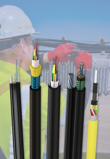 Fiber Optic CableAccess and backbone
 Ethernet CableCat5e to Cat8
 Coaxial CableRF and video signal
 Fire, Security & AlarmSafety systems
 Voice, Audio & VideoSignal cabling
 Power & Control CableEnergy and control
Fiber optic cable systems
Outdoor, indoor, FTTH and distribution cable lines for access networks, backbone routes and campus deployments.
 Telecom & ISP NetworksFTTH, PON, ODN
 Data Center InfrastructureServer room cabling
 Building Low-Voltage SystemsBMS, AV, weak current
 Security & Fire ProtectionAlarm, CCTV, access
 Industrial Automation CablePLC, RS485, fieldbus
 Energy & Power InfrastructureSolar, battery, power
Telecom & ISP Networks
For FTTH / PON access, outdoor fiber deployment, aerial routes, duct routes, direct burial routes, rural broadband and ODN planning.
Tools
Use calculators and planning tools for conduit capacity, PoE voltage drop and fiber optic link loss budget work.