FTTH Installation: Essential Preparation, Tools, Equipment, and Pre-Installation Checklist
Author: Isaac Publish Time: 05-03-2025 Origin: Site
FTTH Installation Checklist: Preparation, Tools and Testing Prepare the route, tools, materials, safety controls, test methods, and records before field work begins.
A reliable fiber-to-the-home installation starts before a cable is pulled or a connector is opened. The installer needs an approved route, compatible passive components, task-specific preparation tools, clean reference cords, suitable test equipment, site access, power arrangements, and a documented acceptance method. Preparing these items in advance reduces avoidable rework and helps the crew protect both the optical link and the people working around it.
The exact toolkit depends on the cable construction, termination method, PON generation, network status, mounting environment, and operator acceptance plan. Confirm those conditions first; do not build the job around a generic tool list.

1. Confirm the Installation Scope
Before packing tools, identify exactly what the crew is expected to install and accept. A subscriber activation may involve only a pre-terminated drop and ONT, while another job may require cable placement, field termination, fusion splicing, enclosure work, optical testing, and indoor equipment mounting.
Confirm the start and end points, assigned ports, route drawing, cable type, fiber count, drop length, and reserve-length rules.
Confirm whether the link is dark, under construction, or carrying live PON traffic.
Identify fusion-spliced, field-installable, and factory-terminated interfaces.
Record connector types and polish: SC/APC, SC/UPC, LC/UPC, or another approved interface. APC and UPC connectors must not be mated together.
Obtain the design optical budget, test wavelengths, pass/fail criteria, required test direction, report format, and naming convention.
Confirm who provides and commissions the ONT, power adapter, router, outlet, and customer-side Ethernet connection.
2. Essential FTTH Installation Tools
Choose each tool for a defined task and for the exact cable or connector in the job. Universal-looking tools may damage an unfamiliar sheath, buffer, strength member, or connector body.
Cable preparation and fiber handling
Cable sheath and drop-cable tools: Use tools approved for the cable profile and entry method so that strength members and fibers are not nicked.
Fiber stripper: Match the stripping tool to the coating or buffer diameter and keep the blades clean and undamaged.
Aramid-yarn scissors: Use them for aramid strength yarn, not to prepare the glass end face.
Precision fiber cleaver: Produce the cleaved glass end required by the approved splice or field-connector procedure.
Tweezers and a fiber-offcut container: Collect glass fragments immediately and prevent them from remaining on clothing or the work surface.

Splicing or field termination
For fusion splicing, prepare a suitable fusion splicer, charged batteries or site power, the correct fiber holders, a cleaver, splice-protection sleeves, a sleeve heater, and any maintenance items required by the splicer manufacturer. The ZCFFSAI-20 fusion splicer is one current ZION option for FTTH and general field work; verify its holders, accessories, environmental range, and approved procedure against the project before use.
For mechanical splices or field-installable connectors, use the manufacturer-approved preparation dimensions, assembly fixture, consumables, and inspection method. Do not substitute a fusion-splice procedure for a mechanical connector procedure. Factory-terminated drops can reduce field termination work, but their connector type, length, pull protection, and route access still need confirmation.
Inspection and cleaning
A video inspection probe with tips that match the plug and bulkhead interfaces.
Connector-specific one-click cleaners or another approved dry-cleaning tool.
Lint-free wipes, approved fiber-cleaning solvent when the procedure requires it, and clean swabs for recessed ports.
Clean caps and protected storage for reference cords, adapters, pigtails, and connectors.
Apply an inspect—clean when necessary—reinspect workflow before mating. IEC 61300-3-35 provides end-face inspection methods and acceptance criteria; the applicable operator or project procedure determines the exact pass/fail configuration.
Optical test equipment
Visual fault locator: Useful for continuity, identification, and visible leakage from some short-link faults. Treat it as a laser source and use it only under the approved safety procedure.
Optical power meter and light source, or OLTS: Used for end-to-end insertion-loss testing with compatible wavelengths, adapters, and reference cords.
PON-selective power meter: Used when the operator's method requires wavelength-selective measurements on an active PON.
OTDR: Used for event location, route length, splice or connector analysis, and troubleshooting when the project method calls for it. Prepare appropriate launch and receive fibers and test settings.

General installation and mounting tools
The route may also require a tape measure or laser distance meter, cable payout support, approved pulling grip, duct rod or fish tape, hand tools, drill and bits, anchors, fasteners, cable clamps, labels, lighting, access equipment, and weather protection. Select drilling and fixing tools for the actual wall, pole, cabinet, or enclosure; they are not optical-fiber preparation tools.
3. Stage the Correct Materials and Equipment
A complete FTTH installation package normally combines cable, connectivity, enclosure, mounting, labeling, and active-equipment items. The actual bill of materials follows the approved network design. ZION's FTTH/PON access network solution shows how drop cable, PLC splitters, fiber access terminals, patching, and related passive components fit into the subscriber path.
Drop cable or pre-terminated drop assembly with the specified construction, length, fiber type, and connector interface.
FAT, terminal box, customer outlet, splice tray, adapter, pigtail, patch cord, splitter, and splice protection as required by the drawing.
Clamps, brackets, ties, anchors, cable-entry seals, conduit accessories, identification labels, and firestopping materials approved for the route.
ONT/ONU, approved power adapter, Ethernet patch cord, and router or gateway when these items are in the installation scope.
Grounding or bonding items where metallic cable members, supports, cabinets, or local rules require them.
Spare consumables and a controlled replacement quantity for connectors, sleeves, cleaning items, blades, batteries, and labels.

4. Establish the Site Safety Plan
Fiber installation combines invisible optical radiation, sharp glass fragments, cutting tools, chemicals, access work, drilling, electrical equipment, traffic, and sometimes outdoor or confined-space hazards. IEC 60825-2 addresses safety for optical-fiber communication systems, but the field plan must also follow the operator's method, equipment instructions, and applicable site rules.
Never look into a fiber, connector, adapter, or instrument port. Optical power may be invisible. Identify and isolate live circuits using an approved instrument and procedure.
Wear suitable eye protection when handling bare fiber or chemicals. Use task-appropriate gloves when working with sharp blades or other identified hazards.
Keep food and drink away from the work area. Collect glass offcuts with tweezers and place them in a dedicated, closed container.
Review safety data and ventilation needs for cleaning products. Keep approved solvents away from ignition sources.
Use qualified personnel, inspected ladders or access equipment, fall protection, traffic control, electrical isolation, and confined-space procedures whenever those risks apply.
Protect occupants and equipment from drilling dust, exposed fibers, open enclosures, trailing cables, and unattended tools.
5. Survey the Route and Device Locations
Walk the intended route before installation. A drawing may not reveal blocked ducts, unsafe access, sharp edges, recent building changes, unsuitable mounting surfaces, water paths, or a customer location with no practical power or Wi-Fi coverage.
Verify route length, duct or pathway condition, access points, building entry, penetrations, pulling direction, and cable reserve locations.
Check the cable manufacturer's loaded and unloaded bend-radius limits, maximum pulling tension, permitted clamp method, and environmental rating.
Identify abrasion, crush, water, UV, rodent, heat, fire-spread, vehicle, and accidental-contact risks along the route.
Confirm required separation and crossing methods near electrical, heating, plumbing, elevator, fire-safety, and other building services.
Place the terminal and ONT where they are dry, ventilated, serviceable, protected from impact, and close to an approved power outlet.
Coordinate the ONT/router position with the customer's Ethernet and Wi-Fi needs rather than choosing a location only because the fiber can reach it.
Confirm permits, access windows, resident appointments, shutdowns, and restoration responsibilities before dispatch.
6. Pre-Installation Readiness Checklist
Documents: Approved drawing, route, port assignment, work order, method statement, safety plan, optical budget, test plan, labels, and report templates are available to the crew.
Cable and components: Part numbers, quantities, connector polish, adapter type, splitter ratio, enclosure capacity, mountings, and consumables match the design. Packaging and reels show no transport damage.
Tools: Preparation and mounting tools match the cable and hardware. Blades, holders, heaters, batteries, electrodes, chargers, spare parts, and cleaning supplies are ready.
Test equipment: Instruments cover the required wavelengths and measurement range; adapters, inspection tips, reference cords, launch/receive fibers, software, storage, clock, and calibration status are checked.
Site: Route access, mounting surfaces, entry points, lighting, weather, working-at-height arrangements, electrical risks, power outlets, and customer access have been confirmed.
Safety: The crew understands live-fiber identification, glass disposal, tool handling, chemical controls, isolation, barriers, PPE, emergency contacts, and stop-work conditions.
Handover: The team knows which results, OTDR traces, power readings, end-face records, photographs, labels, serial numbers, route changes, and customer sign-off must be captured.
7. Plan Testing and Acceptance Before Installation
Testing is most useful when the acceptance method is agreed before the work begins. Inspect connectors and test cords before mating, then clean and reinspect when necessary. For installed-link loss, use a compatible light source and power meter or OLTS according to the project method. For live PON activation, use the operator-specified wavelength-selective procedure and compare the result with the approved power window.
An OTDR provides valuable information about length, events, reflections, splices, connectors, bends, and fault location, but it does not replace direct end-to-end insertion-loss measurement when that measurement is required. Short FTTH drops, splitter networks, and live systems also require suitable launch conditions, wavelengths, dynamic range, filtering, and trained trace interpretation. The FTTH drop-cable testing and acceptance guide provides additional test-planning context; the signed project requirements remain the acceptance authority.
Do not copy a universal dB limit into every FTTH job. Compare measured results with the designed link loss, component specifications, PON class, operator method, and project acceptance criteria. Save results with a clear link ID, direction, wavelength, reference method, instrument, date, and technician.
8. Common Preparation Mistakes
Using scissors instead of a precision cleaver to prepare the glass fiber end.
Assuming every flat drop cable uses the same stripper, clamp, bend limit, or pulling method.
Mating APC and UPC interfaces or bringing the wrong inspection-probe tip and adapter.
Connecting a dust-capped end face without inspection because the connector appears new.
Using contaminated reference cords and then treating poor test results as installed-cable faults.
Using an ordinary broadband meter or OTDR on an active PON without confirming wavelength, filtering, and operator procedures.
Treating an OTDR estimate as the only end-to-end loss acceptance result.
Arriving without power, charged batteries, labels, spare consumables, access approval, or a defined result-storage method.
Frequently Asked Questions
What are the minimum tools for a basic FTTH drop installation?
The minimum set depends on whether the drop is pre-terminated, mechanically terminated, or fusion-spliced. It normally includes cable-specific preparation tools, cleaning and inspection tools, safe glass disposal, mounting tools, identification materials, and the test instruments required by the operator. A fusion-spliced job also needs a compatible splicer, cleaver, holders, sleeves, and heater.
Can scissors be used to cut optical fiber?
Aramid-yarn scissors are used for strength yarn. A precision fiber cleaver prepares the glass end required for fusion splicing or an approved field-termination process. Follow the connector or splicer procedure for the required cleave length and quality.
Is an OTDR enough to accept an FTTH link?
Not automatically. An OTDR is valuable for locating and analyzing events, but direct insertion-loss or live PON power measurements may also be required. Use the instruments, wavelengths, reference method, direction, and limits specified by the network owner or acceptance plan.
How should the FTTH cable bend radius be selected?
Use the cable manufacturer's specified minimum bend radius for the installed condition. The limit may differ while the cable is under pulling tension and after it has been placed. Also check connector boot, enclosure, splice-tray, and local routing constraints.
What records should be delivered after installation?
The handover package may include link and port IDs, route changes, cable and connector details, splice records, end-face inspection results, insertion-loss or PON power readings, OTDR traces when required, instrument details, photographs, labels, ONT serial information, and customer or supervisor sign-off.
Conclusion
FTTH preparation is a controlled readiness process, not just a list of hand tools. Confirm the network scope, cable and connector interfaces, route conditions, safety controls, component compatibility, test method, and handover records before dispatch. When each tool and measurement has a defined purpose, the installation team can work more safely, identify problems earlier, and deliver results that can be checked against the approved design.



 Fiber Optic Tools
Products 6 families
Solutions 6 markets
Resources Tools & docs
Certificate
Certification and compliance references for project review, qualification and purchasing documentation.

 Fiber Optic CableAccess and backbone
 Ethernet CableCat5e to Cat8
 Coaxial CableRF and video signal
 Fire, Security & AlarmSafety systems
 Voice, Audio & VideoSignal cabling
 Power & Control CableEnergy and control
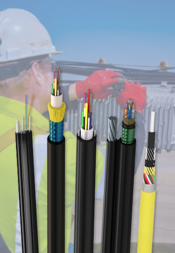
Fiber optic cable systems
Outdoor, indoor, FTTH and distribution cable lines for access networks, backbone routes and campus deployments.
 Telecom & ISP NetworksFTTH, PON, ODN
 Data Center InfrastructureServer room cabling
 Building Low-Voltage SystemsBMS, AV, weak current
 Security & Fire ProtectionAlarm, CCTV, access
 Industrial Automation CablePLC, RS485, fieldbus
 Energy & Power InfrastructureSolar, battery, power
Telecom & ISP Networks
For FTTH / PON access, outdoor fiber deployment, aerial routes, duct routes, direct burial routes, rural broadband and ODN planning.
Tools
Use calculators and planning tools for conduit capacity, PoE voltage drop and fiber optic link loss budget work.