Where are signal and control cables used in wind turbines?
Author: Site Editor Publish Time: 10-09-2016 Origin: Site
Where Are Signal and Control Cables Used in Wind Turbines? Signal and control cables connect sensors, controllers, actuators and communication equipment throughout the blades, hub, nacelle and tower. Their selection depends on signal type, movement, shielding, temperature, oil exposure, fire performance and the turbine OEM's installation design. |
Where Signal and Control Cables Are Used
Most wind turbine signal and control wiring is concentrated in the rotor, nacelle and tower. These circuits carry measurement values, status information, operating commands and industrial communication data rather than bulk generated power. The exact architecture varies by turbine platform, but the main application zones are consistent.
Blades and hub Sensor and actuator cables serve blade pitch position, pitch-drive feedback, limit switches, temperature sensing and other blade or hub monitoring functions. These routes may experience repeated movement, tight installation space and centrifugal vibration. |
Nacelle machinery Control cables connect temperature, vibration, speed, position, pressure and oil-condition sensors to local controllers and condition-monitoring equipment. Commands and feedback also serve the yaw system, cooling fans, pumps, brakes, converter auxiliaries and safety circuits. |
Tower and tower base Signal, control, Ethernet and fiber links connect nacelle equipment with tower-base control cabinets, converters, service systems and the wind-farm communication network. Cable routing must account for vertical support, separation from power circuits and the torsion zone below the nacelle. |
What Types of Cables Are Used?
A turbine normally uses several cable families because low-level analog measurements, discrete control signals, safety circuits and digital networks have different electrical and mechanical needs. Common categories include:
Multicore control cable for relays, contactors, switches, operating commands and general low-voltage control circuits.
Twisted-pair instrumentation cable for analog sensors and measurement loops where pair geometry and noise control matter.
Sensor and actuator cable for compact field connections, including feedback devices and machine-mounted components.
Fieldbus or industrial Ethernet cable for protocol-based communication between controllers, remote I/O, drives and network equipment.
Fiber optic cable where electrical isolation, long vertical links or immunity to electromagnetic interference is required.
ZION's current control cable range includes flexible control, fieldbus, industrial Ethernet, PROFINET and sensor/actuator cable families. Final selection still depends on the turbine drawing, protocol, movement level and required approvals.

Shielding and EMC in the Nacelle
The nacelle contains generators, converters, motors, switching devices and long cable routes, so electromagnetic compatibility is an important system-level design task. Shielded cable can reduce capacitive and radiated coupling, but the shield works only as part of a coordinated installation.
Engineers should confirm pair twisting, overall or individual shielding, shield coverage, transfer impedance where specified, gland or connector termination, bonding, grounding and the required separation from motor or converter power cables. A universal instruction to ground every shield at one end or both ends is unsafe because the correct method depends on signal frequency, equipment interfaces, equipotential bonding and the OEM's EMC design.
IEC 61000-6-2 provides generic immunity requirements for industrial environments when no dedicated product or product-family standard applies. The finished turbine and equipment requirements—not the cable shield alone—determine the required immunity and emission performance.
Mechanical and Environmental Requirements
A cable that performs well in a stationary control cabinet may not survive a wind turbine's moving zones. The specification should identify the real duty rather than relying on general terms such as “flexible” or “oil resistant.”
Torsion and movement: define twist angle, active length, cycle count, temperature and test method for routes affected by nacelle yaw or moving pitch equipment.
Vibration: use conductor, insulation, shielding and strain-relief designs validated for the mounting location and expected vibration spectrum.
Oil and chemicals: identify the fluid, exposure temperature and test classification; a generic oil-resistance claim does not cover every lubricant or hydraulic fluid.
Temperature: confirm operating and installation temperature, cold bend or cold impact requirements, and flexing performance at the lowest expected temperature.
Ozone, UV and moisture: specify these only where the cable route is exposed; indoor nacelle and outdoor tower routes may require different jackets.
Fire performance: match flame, smoke and halogen requirements to the jurisdiction, turbine specification and installation method.
Installation Practices That Protect Signal Quality
Route low-level signal and communication cables separately from high-current motor, generator and converter cables according to the OEM's EMC plan.
Maintain the manufacturer's minimum bend radius during pulling, installation and operation.
Use compatible glands, connectors and shield terminations so the cable's mechanical and EMC design continues through the enclosure entry.
Provide strain relief and vertical support without crushing the jacket, deforming pairs or loading connector contacts.
Keep the designed torsion or service loop free from clamps, sharp edges and unintended contact with moving machinery.
Label both ends and record cable type, route, shield termination and test results for maintenance and replacement.
Standards and Approval Context
IEC 61400-1 addresses wind turbine design requirements, including control and protection functions and internal electrical systems. It establishes the turbine-level context but does not replace the product standard or qualification program for each cable.
IEC 61400-25 defines information models and communication principles for monitoring and control between wind-power-plant components and actors such as SCADA systems. It should not be cited as proof that a specific internal Ethernet, fieldbus or sensor cable construction is approved; internal communication within a turbine component is outside the series' normative scope.
For North American projects, Wind Turbine Tray Cable is associated with UL Subject 2277. The cable's complete marking and certification scope must be checked for conductor type, voltage, wet/dry rating, oil resistance, flame performance and permitted installation. Other cable categories may apply to instrumentation, communication, optical fiber or flexible circuits. The locally adopted electrical code and turbine certification requirements determine what is acceptable.
Signal and Control Cable Specification Checklist
Provide these details before requesting a cable recommendation or quotation:
circuit function: sensor, analog measurement, discrete control, safety, fieldbus, Ethernet or fiber;
voltage, current, conductor size, pair/core count and required electrical performance;
protocol, impedance, category, data rate and maximum channel length where applicable;
shielding, grounding, bonding and connector or gland requirements;
fixed, occasional movement, continuous flexing or torsion duty with test parameters;
temperature, vibration, oil/chemical exposure, UV, ozone and moisture conditions;
flame, smoke, halogen, listing and jurisdictional requirements;
drawing, route length, termination details, test reports and documentation required for approval.
Frequently Asked Questions
Why are shielded cables used in wind turbine nacelles?
Shielding can reduce electromagnetic coupling from converters, motors and power cables into sensitive signal circuits. Effective protection also requires correct routing, shield continuity, bonding and termination.
Do all signal cables need torsion resistance?
No. Torsion resistance is required for cables routed through zones that twist during yaw or other movement. Fixed cabinet wiring may need vibration resistance and flexibility for installation without requiring the same torsion-cycle qualification.
Can standard Ethernet cable be used from the nacelle to the tower base?
Only when its transmission performance, movement rating, length, shielding, temperature, fire rating and installation method match the turbine design. Fiber is often considered when electrical isolation or EMI immunity is more important.
Is oil resistance the same for every control cable?
No. Oil-resistance markings refer to defined test conditions. Confirm the fluid type, exposure temperature, duration and applicable cable standard before selecting a jacket material.
What information is needed to select a wind turbine control cable?
Start with the circuit function, protocol, electrical rating, number of cores or pairs, shielding, movement, environment, route length, terminations and target approval. The turbine OEM drawing and qualification requirements should control the final specification.



 Fiber Optic Tools
Products 6 families
Solutions 6 markets
Resources Tools & docs
Certificate
Certification and compliance references for project review, qualification and purchasing documentation.

 Fiber Optic CableAccess and backbone
 Ethernet CableCat5e to Cat8
 Coaxial CableRF and video signal
 Fire, Security & AlarmSafety systems
 Voice, Audio & VideoSignal cabling
 Power & Control CableEnergy and control
Fiber optic cable systems
Outdoor, indoor, FTTH and distribution cable lines for access networks, backbone routes and campus deployments.
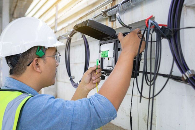 Telecom & ISP NetworksFTTH, PON, ODN
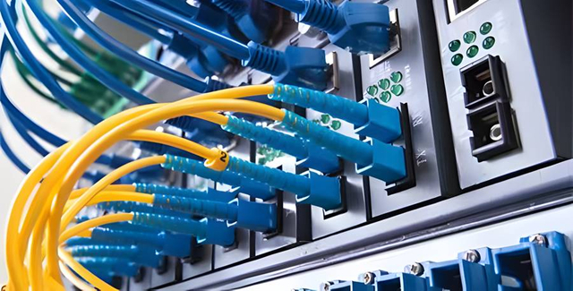 Data Center InfrastructureServer room cabling
 Building Low-Voltage SystemsBMS, AV, weak current
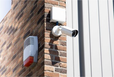 Security & Fire ProtectionAlarm, CCTV, access
 Industrial Automation CablePLC, RS485, fieldbus
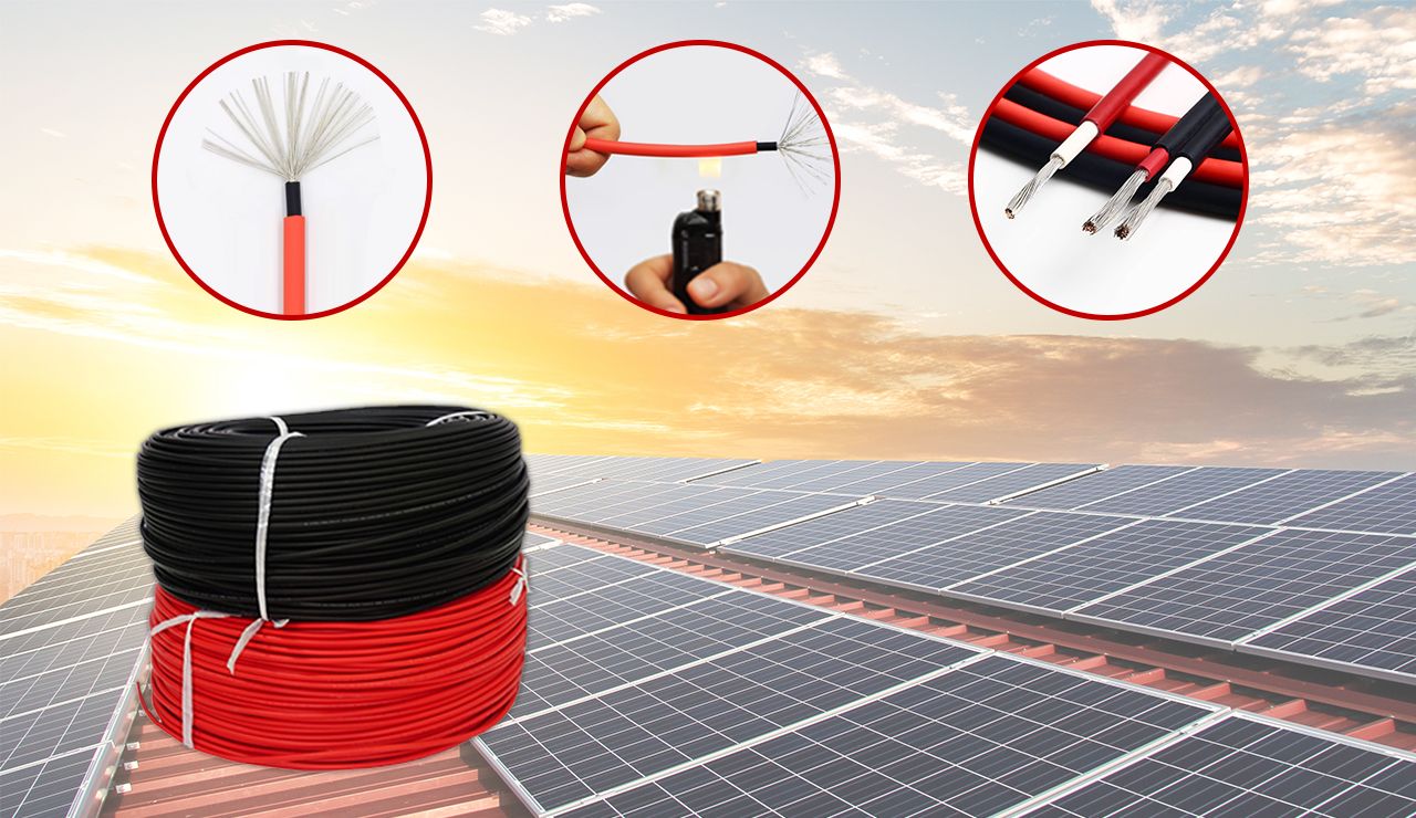 Energy & Power InfrastructureSolar, battery, power
Telecom & ISP Networks
For FTTH / PON access, outdoor fiber deployment, aerial routes, duct routes, direct burial routes, rural broadband and ODN planning.
Tools
Use calculators and planning tools for conduit capacity, PoE voltage drop and fiber optic link loss budget work.