News Details
Common MPO Polarity Mistakes and How to Avoid Them
Author: James Publish Time: 30-03-2026 Origin: Site
Common MPO Polarity Mistakes and How to Avoid Them
A practical guide for engineers, buyers, and project teams to identify the most common MPO polarity mistakes before they create link failures, rework, or avoidable troubleshooting costs.
Most MPO polarity failures come from end-to-end design mismatch, not from one single bad component.
Trunk, cassette, harness, adapter orientation, and male/female gender must be checked as one complete channel.
Field verification is cheaper than rework. Inspect, confirm mapping, and test before blaming the hardware.
■ 1) What MPO Polarity Mistakes Really Mean
In an MPO link, polarity is not just a patch cord issue. It is the end-to-end logic that makes sure transmit fibers land on the correct receive fibers after the full path is assembled. That path may include trunks, cassettes, harnesses, adapters, and breakout sections.
Most failures happen when the team verifies only one part in isolation. A trunk may be correct by itself, and a cassette may also be correct by itself, but the complete link can still fail if they belong to different polarity assumptions or different mapping logic.
■ 2) Architecture: Trunk, Cassette, Harness, and Breakout
One of the biggest sources of confusion is assuming that all MPO components do the same job. In reality, each component plays a different role in routing, distribution, and interface conversion. Misunderstanding that role is often the first step toward a polarity error.
| Component | Primary Role | Typical Risk | Engineering Note |
|---|---|---|---|
| MPO Trunk Cable | High-density backbone connection between panels or zones | Wrong polarity type or key orientation | Must match the chosen end-to-end polarity method |
| MPO Cassette | Converts MPO to duplex interfaces such as LC | Wrong cassette polarity versus trunk design | Do not treat all cassettes as universal |
| MPO Harness Cable | Breaks out MPO into multiple equipment-side connectors | Lane mapping mismatch | Often used near active equipment, so lane logic matters more |
| Direct Breakout Assembly | Direct branch routing without cassette conversion | Used where a cassette-based design was expected | Good for direct connections, but only when intentionally designed |
■ 3) How MPO Polarity Works in Practice
In practice, MPO polarity is the controlled relationship between fiber position, connector orientation, and application mapping. The job is simple in principle: every transmit path must reach the intended receive path. The challenge comes from the number of parts involved and the fact that each part may alter orientation or interface type.
The safest way to manage this is to define the polarity method at design stage, confirm the gender of each mating pair, and keep a clear channel drawing that procurement and installation teams can follow without interpretation.
| Check Item | Why It Matters | Typical Error | Result |
|---|---|---|---|
| Polarity Method | Determines channel mapping logic | Mixing method assumptions | Tx/Rx misalignment |
| Key Orientation | Controls connector mating direction | Wrong orientation in assembly | Unexpected lane reversal |
| Male / Female Gender | Controls physical mating compatibility | Both sides pinned or both sides unpinned | Cannot mate or unstable interface planning |
| Application Mapping | Defines how fibers are used by equipment | Using wrong cassette or harness for the application | Link failure or incorrect breakout behavior |
What engineering teams should document before deployment
Chosen polarity method for the full channel
Trunk type, connector orientation, and fiber count
Cassette or harness mapping logic
Male/female connector gender at every mating point
Expected application type, such as duplex breakout or parallel optics
■ 4) The 5 Most Common MPO Polarity Mistakes
1. Mixing polarity methods inside one link
This is the most common design error. Teams select a trunk based on one polarity method, then add cassettes or patching that were chosen for another method. Each part may be “correct” in isolation, but the complete channel is not.
2. Misapplying trunk, cassette, and breakout logic
A trunk-based structured cabling design should not be solved later by random breakout substitution. If the design intent was cassette-based distribution, replacing that with the wrong harness or breakout assembly often creates lane and mapping confusion.
3. Male/female connector mismatch
Even when polarity is planned correctly, the channel can still fail physically if the gender of the connectors is wrong. This is a fast way to create installation delays and emergency reordering.
4. Assuming all fiber counts map the same way
Different applications do not always use the same lane structure. A design that works for one mapping logic may not work for another. Teams that move between multiple fiber-count environments without checking the application mapping often create avoidable faults.
5. Skipping field verification
Labels are helpful, but they are not a substitute for inspection and testing. Wrong patch positions, contamination, or swapped assemblies can look like polarity failures until the link is checked systematically.
| Mistake | Where It Usually Happens | Immediate Risk | Cost Impact | Prevention Method |
|---|---|---|---|---|
| Mixed polarity methods | Design and procurement | Wrong Tx/Rx routing | Rework, retesting, delayed commissioning | Lock one method for the full channel |
| Trunk/cassette/breakout mismatch | Architecture selection | Wrong mapping path | Extra adapters, extra labor, reduced clarity | Define the architecture before BOM release |
| Male/female mismatch | Ordering and installation | Mechanical incompatibility | Rush replacement and installation delay | Check gender at every mating pair |
| Wrong application mapping | System design | Lane assignment error | Troubleshooting time and uncertain root cause | Select by application, not connector appearance |
| No field verification | Commissioning | Unclear failure diagnosis | Longer downtime and repeated handling | Inspect, clean, and test segment by segment |
■ 5) Decision Rules / Engineer’s Shortcut
This section is designed for quick engineering review. If the project team can answer the questions below clearly, the chance of polarity-related deployment mistakes drops significantly.
| Decision Question | If Yes | If No | Recommended Action |
|---|---|---|---|
| Is one polarity method defined for the full channel? | Proceed to component verification | Stop BOM approval | Publish a channel drawing before ordering |
| Is the architecture clearly trunk + cassette, trunk + harness, or direct breakout? | Check mapping consistency | Expect integration confusion | Choose one architecture based on equipment access strategy |
| Have all MPO mating points been checked for male/female compatibility? | Proceed to field preparation | High chance of installation stop | Review every connector interface in the BOM |
| Does the cassette or harness match the application mapping? | Proceed to testing plan | Risk of lane mismatch | Select by equipment application, not by connector type alone |
| Is a field verification workflow defined before commissioning? | Commissioning will be faster and cleaner | Root cause analysis will be slower | Add inspection, cleaning, and staged testing to the work order |
■ 6) On-Site Troubleshooting Method
When the link does not come up, random patch swapping usually makes the problem harder to diagnose. A controlled troubleshooting sequence is faster and reduces handling risk.
Step 1: Confirm the intended channel design
Verify the planned polarity method, channel drawing, and equipment-side mapping. Start with the design intent, not with assumptions made on site.
Step 2: Check connector gender and orientation
Make sure every MPO mating pair is mechanically compatible and installed with the intended orientation.
Step 3: Inspect and clean
Contamination can look like a polarity problem. End-face inspection and cleaning should happen before replacing parts.
Step 4: Test segment by segment
Check the trunk first, then the cassette or harness, then the final patching section. Isolating the fault zone is more effective than changing multiple variables at once.
■ 7) Application Scenarios
MPO polarity control matters most in projects where density is high, commissioning time is limited, and channel documentation needs to support future maintenance.
| Scenario | Why Polarity Matters | Main Deployment Concern | Recommended Priority |
|---|---|---|---|
| Data Center Backbone | High density and repeatable channel logic | Wrong trunk/cassette combination | Document the full channel before procurement |
| Equipment Breakout Zone | Lane mapping affects port availability | Wrong harness or breakout selection | Match harness logic to equipment application |
| Migration or Expansion Project | Legacy links and new links may not follow the same assumptions | Mixed method risk | Audit old channels before integrating new hardware |
| Third-Party Integration | BOM clarity becomes critical when multiple vendors are involved | Naming mismatch and unclear connector gender | Require a verified mapping sheet from all parties |
■ 8) FAQ
1. Can I mix different MPO components if the connector type looks the same?
No. Connector appearance alone does not confirm mapping compatibility. Trunks, cassettes, harnesses, and breakout assemblies must be selected according to one end-to-end design logic.
2. Is male/female connector checking really necessary during procurement?
Yes. Gender mismatch is a common reason for installation delays. Every MPO mating point should be verified before shipment, especially in multi-vendor projects.
3. What is the fastest way to reduce polarity risk on a new project?
Create a one-page channel map that shows the polarity method, component roles, gender, and application mapping. This document should guide both ordering and installation.
4. How should I handle a mixed legacy and new MPO environment?
Audit the existing links first. Do not assume old installations follow the same logic as new designs. A migration plan should verify mapping, labeling, and mating compatibility before expansion.
5. Can suppliers support custom mapping, harness options, or project verification?
Yes, but custom assemblies should be based on a confirmed project drawing. For B2B projects, it is better to confirm application logic, connector type, fiber count, and deployment environment before production.
■ 9) Conclusion
Most MPO polarity mistakes are not complicated, but they are expensive. They usually come from mixed design assumptions, unclear component roles, or incomplete verification before installation.
The most effective way to avoid these errors is to treat the MPO link as one engineered channel. Define the polarity method early, verify trunk and cassette logic together, confirm male/female mating points, and require a field testing workflow before commissioning.
For engineers and project teams, this approach reduces troubleshooting time. For buyers and integrators, it lowers rework risk and improves delivery confidence.
Send your application type, connector format, fiber count, breakout requirement, and deployment environment. The ZION team can help review selection logic for trunk, cassette, harness, and related MPO assemblies.
-
 [Security&Fire Protection] Security Cable RFQ Checklist for LATAM ProjectsPrepare a complete security cable RFQ for LATAM projects before ESS+ Colombia 2026, covering CCTV, access control, alarm, fire cable, shielding, jacket, certificates, packing and delivery terms. Read More
 -
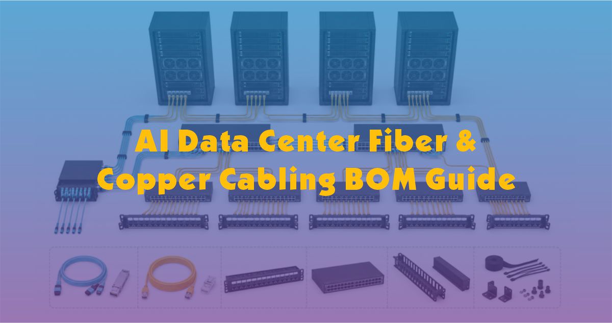 [Copper Communication] AI Data Center Fiber & Copper Cabling BOM GuideLearn why AI data centers need structured fiber and copper cabling BOMs to plan backbone links, management networks, rack cabling, patch panels, labeling, spare capacity and future upgrades. Read More
 -
 [Cable Buyer Guide] Cable RFQ Checklist for Changing Copper & Freight CostsLearn how to prepare a complete cable RFQ when copper and freight costs change, including conductor, length, jacket, fire rating, shielding, packing, delivery terms, samples and certificates. Read More


