OEM customized production according to your requirements.
Standardized products and services according to our own brand.
Standardized products and services according to our own brand.
Author: Site Editor Publish Time: 27-08-2024 Origin: Site
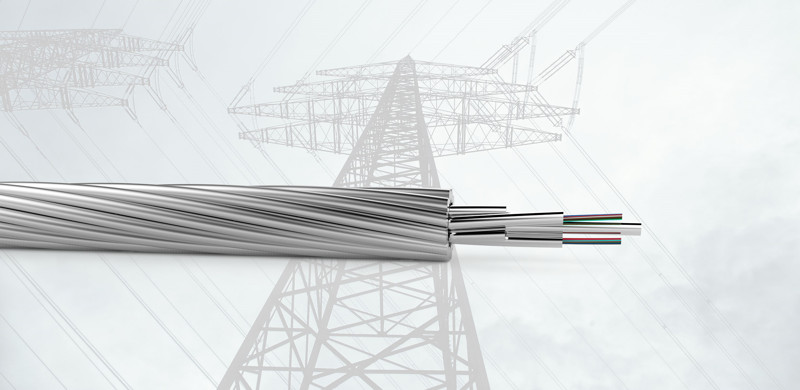
This manual is formulated in accordance with IEEE 1138 - 2008 and IEEE 524 - 1992, etc. OPGW has dual functions of aerial ground wire and fiber communication. It is composed of AS wire, AA wire
and stainless steel tube optical unit. The installation rules of OPGW are basically the same as the engineering and installation modes of traditional aerial power lines. Refer to the installation technology and management of power
company's aerial transmission lines and other related documents.
OPGW is usually installed on the top of power line towers. Adverse factors such as wind vibration, hurricanes, ice thickness, unstable operation caused by temperature, and possible lightning strikes and short circuits should be
considered. A detailed engineering plan should be formulated according to different OPGW structures and specific line conditions. According to the design requirements, OPGW should be correctly configured.
Each reel of optical cable should be installed in the designated part of the line and laid according to the engineering drawing operation file.
In principle, the tension pay-off method is adopted. Maintaining appropriate tension makes OPGW hang in the air, avoiding ground abrasion, reducing green compensation, reducing physical labor,
and increasing engineering speed. According to the engineering capacity, appropriate equipment and tools are configured.
The design department should provide the design drawings to the engineering department. The engineering department compiles the OPGW cable engineering plan (or operation guide including spanning chart and schedule)
according to the line, length, and pre-reserved joint position, checks the relevant data,masters the composition of the entire communication system and the detailed configuration and connection mode of each substation
(including installation methods and specific positions from terminal poles to terminal machine rooms), determines the structure, quantity and accessory configuration, and proposes a suitable erection method according
to the special circumstances of a specific area. Master the mechanical properties, transmission performance and splicing loss and other parameters of OPGW, and prepare data such as reports before acceptance for
on-site testing and delivery inspection.

2.1. Recommended main operation equipment and transportation tools (for one team):
Including tension machine, traction machine, pay-off machine, pulley, tensionless steel wire, traction net, torsion releaser, anti-torsion whip, pre-stranding wire for tightening, intercom, radio station, sag board,
theodolite, hand chain block, telescope, etc. Before the project, auxiliary facilities such as transportation tools, cranes, climbing boards, safety helmets, safety belts, grounding wires, electroscopes, ropes, red and white flags,
bamboo, protection nets, and safety warning signs should also be prepared.
NO | Name | Quantity | Specification | Notes |
1 | Tension Machine | 1 | 3.5t | Flexible Range |
2 | Traction Machine | 1 | 3t | Flexible Range |
3 | Pay-off Machine | 2 | 5t | |
4 | Pulley | 20 | Diameter of the groove is 600/800mm | |
5 | Tensionless Steel Wire | 7000 | Match with Diameter of the cable | |
6 | Traction Net | Several | Match with the cable | Match with the Number of the cable |
7 | Torsion Releaser | 2 | Match with the cable | |
8 | Anti-torsion Whip | 2 | Optional | |
9 | Tightening Pre-stranding Wire | Several | Match with the cable diameter | Match with the Number of the cable |
10 | Interphone | 20 | Advised Amount | |
11 | Radio Station | 2 | Advised Amount | |
12 | Sag Board | 4 | Advised Amount | |
13 | Theodolite | 1 | Advised Amount | |
14 | Hand Chain Block | Several | Determined by Constructer | |
15 | Telescope | 2 | 300 times |
2.2. Key points of engineering equipment:
① Traction and tension machine operation:
The traction and tension machine should have tension indication and limiting devices that can adjust tension and pay-off speed at any time so that OPGW can operate at a specific tension value. It should have a flexible braking
device that can maintain the original tension of OPGW when the machine is stopped momentarily. In principle, a self-protection braking device should be used. The groove of the tension machine should be semi-circular.
The recommended depth should be not less than 50% of the OPGW. The angle between the wall and the middle vertical line should be between 5° and 15°. The diameter should be more than 70 times but not less than 1200mm
of the diameter of OPGW. To prevent damage to the outer stranded wire, chloroprene rubber should be wrapped in the groove. OPGW should be wrapped at least 6 circles and fastened on the tension pulley.
After the OPGW is pulled out from the drum, it cannot be directly wrapped on the tension machine. First, a tightrope should be wrapped on the tension machine and then the cable is pulled to avoid artificial cable torsion.

② Pulley:
During installation and splicing, the minimum allowable bending radius should be about 20D. It is recommended to use pulleys with diameters of 600mm and 800mm to ensure no damage to the cable.
The width of the pulley groove should not be less than the diameter of the cable and should be as large as possible. At no time should it be less than the minimum dynamic bending radius. To increase wear resistance
and prevent OPGW from rotating in the groove, the pulley groove should be coated with a chloroprene rubber elastic buffer layer. The edge of the pulley support should be smooth or protected by colloid. The gap of the pulley
should be less than 10mm to prevent damage to the cable surface or cable jamming. The pulley should be in good condition and properly lubricated to ensure smooth operation of OPGW and reduce wear on the outer
stranded wire. The cushion layer cannot be damaged, aged or peeled off. When installing OPGW, the pulley is usually grounded. At least the pulleys at the two towing sections should be grounded with the tower at the same time. The pulley is usually connected with the tower, hook, etc. In addition, the use of thimble clevis to hang the hanging ring and other accessories ensures its free movement. However, the tension and type of pulley often determine the use of the thimble.

③ Traction net:
Used to tow the OPGW cable smoothly through the pulley. It is composed of two or three layers of stranded hollow tubes. The inner diameter should correspond to the cable. During towing, the traction force should
be the same as the pay-off tension. The use of the traction net should strictly follow the manufacturer's instructions. It is not allowed to adjust the tension with the traction net or hold the cable when adjusting the tension.

④ Anti-torsion whip
Often used with the traction net. Its weight length should be above 5N.m to prevent OPGW from rotating during traction and protect the excess fiber length from damage. It can also avoid torsion release,
degumming and bird cage phenomenon, and protect the cable from damage. The traction torsion releaser is used to protect the traction rope from knotting.

⑤ Pre-stranding wire for tightening:
Used temporarily for pre-tensioning to adjust tension and sag. It can be reused more than 3 times.

2.3. Transportation and storage of optical cable reels:
OPGW cable should be packaged in wooden or iron-wooden drums with wooden materials.
During transportation and storage, the following matters should be noted:
① Store in a dry and ventilated indoor place. If indoor storage is not possible, choose a flat, solid, and well-drained place.
② In rainy seasons, cover with waterproof cloth to avoid deformation and rot after long-term rain. In dry seasons, if the wooden materials shrink after long laying, check the drum before laying.
③ If possible, soak the cable in water one day before laying. Take effective measures to prevent moths and other harmful insects.
④ The cable drum cannot be rolled more than 5m. Roll according to the printed rotation arrow on the drum for short distances.
⑤ The cable must be transported, loaded and unloaded by special vehicles (cranes and forklifts). During the process, the cable drum must be vertical to avoid damage to the wooden lagging.
⑥ Do not push the cable drum from the vehicle to the ground by manpower.
⑦ During transportation, the cable end should be fastened. After the cable drum arrives at the installation site, the wooden lagging and other protective facilities can be removed.
⑧ Cable drums are prohibited from being stacked and placed upside down. No other materials are allowed to be placed on the drum.

2.4. On-site inspection and acceptance of OPGW and hardware and accessories before acceptance:
① After the OPPC and hardware and accessories arrive at the construction material warehouse, the construction unit should conduct unpacking acceptance inspection together with the owner, supervisor and supplier representative. Check the attenuation of the OPPC cable, the number of hardware and accessories, types and appearance. After on-site inspection is qualified, all parties perform the signature handover procedure.
② Opening test of OPPC: Use an optical time domain reflectometer (OTDR) to check the continuity, length and attenuation of the optical fiber. Generally, check the wavelength of 1550nm. Record and keep the test results (optical fiber backscattering curve). Only after the cables are tested qualified can they be erected.
③ Checking of hardware and accessories: Each construction section should check, classify and trial-install the hardware and accessories according to the design drawings and technical agreements. Replace the products in time if there are problems. The material keeper should issue materials according to the requirements of the design drawings.
2.5. Staff training:
Conduct power industry technology management rules, power safety regulations, and on-site overhaul rules training. Effectively train engineering operators and laboratory technicians with this manual. Engineers should study and communicate with each other before construction. Technicians or supervisors should explain the structure, performance, quality criteria, engineering procedures, requirements for installation tools, special attentions during installation and use methods of hardware and accessories. Operation demonstrations and trial installations can be used when necessary (such as tension clamps and suspension clamps). Discuss the installation methods under special circumstances.
The tension pay-off method is adopted. This method makes OPGW receive constant tension during the entire pay-off process through the pay-off system, keeping a sufficient distance from obstacles and other objects to avoid friction and protect OPGW. It also reduces physical labor and increases the project speed.

2.1. Handling of pay-off channels, obstacles, crossing agreements and safeguard procedures:
Conduct in accordance with the relevant provisions of "Overhead Transmission Lines Design Technical Procedures" and "Power Line Construction and Acceptance Interim Technical Specifications". Before construction, determine the line channels and find out obstacles and crossing points. Sign crossing agreements and build protection frames in advance for crossings such as railways, expressways, rivers, uninterrupted lines, communication radio lines, streets, and fruit-bearing forests. Try not to damage surrounding crops. When crossing other lines, avoid contact and being pulled by load-carrying insulation ropes to prevent short-circuit accidents. Survey the streets and bridges that the tension-stringing equipment passes through and repair them if necessary.

2.2. Arrangement of traction site and tension site:
① The tension site is usually a field with a width of 10m and a length of 25m, which is convenient for storing and transporting tension machines, cable reels and other materials and facilities.
② The traction site can be the same as the tension site. The tension site and traction site should be located outside the tension towers at both ends of the erection section and in the line direction. If restricted by geography,
they can be on the inside.
③ The distance between the traction machine and tension machine to the first fundamental tower should be at least 3 times the height of the tower. The distance between the tension machine and the spool of the pay-off
stand should not be less than 5m.
④ The force direction of the traction machine wheel, tension machine pulley, cable pay-off stand, pulling rope and pulling rope drum should be perpendicular to the axis and avoid direction changes in the pulley.
⑤ The traction machine, tension machine and cable pay-off stand should be anchored as required.

2.3. Hanging the pay-off pulley:
Hang a pulley that meets the dimensional requirements on each tower according to the OPGW construction technical requirements. For the first fundamental tower, corner tower close to the traction site and tension site, and the tower where the cable cannot meet the envelope angle requirement of the pulley due to large height difference, hang a pulley with a tank bottom diameter of more than 800mm (or a combined pulley block with a diameter of 600mm). During corner tower pay-off, the pulley has a period of leaning from the vertical direction to the corner inside, which is unstable. To avoid cable jumping out of the groove due to the impact of the anti-torsion whip on the pulley and causing thread jamming, the pulley can be pre-leaned inside.
2.4. Laying and levitation of pulling rope:
The pulling rope is laid in sections manually according to the drum length and then connected by a bending resistance connector. This process must be supervised by a specialist. After that, check whether the fair line of the pulling rope is intact. Before using the pulling rope connector, check for fractures and deformations. Non-conforming products are strictly prohibited. After the laying of the pulling rope is completed, it should be raised to the groove of the pay-off pulley.
2.5. Traction end connection:
During pay-off, the fibers in the OPGW can be easily affected and damaged due to extra torsion of OPGW. Therefore, the traction end needs to be properly processed to ensure that OPGW does not have torsion during pay-off. The cable cannot be directly wrapped on the tension machine after being pulled out from the drum. First, use a tightrope to wrap on the tension machine and then draw the cable to
avoid artificial cable torsion. The connection method of the cable with the pulling rope after passing through the tension machine is:
cable - traction net pipe - bending resistance connector - anti-torsion whip (optional) - spiral connector - traction rope.
If OPGW is stranded type, anti-torsion whip is not necessary. Instead, two spiral connectors are used to connect in series through a steel wire rope.

If OPGW is center type, a suitable anti-torsion whip is required. It cannot be installed reversely and should slow down when passing through the pulley. The traction net pipe must match the outer diameter of the cable
to ensure tightness between the net pipe and the cable. It is better to wrap the end of the net pipe with iron wire (not less than 30 turns) and then wrap it with black tape.

3.1. Inspection and requirements before laying:
① Check the location, width, length, structural firmness and overall stability of the crossing frame.
② Check the arrangement of the traction site and tension site and the anchoring situation of the machines.
③ Check whether all staff are in place, whether the communication is smooth and whether there are faults along the line.
④ Ensure that the traction machine and tension machine operate normally, the braking equipment and safety devices are reasonable, and the central shaft of the pay-off stand is horizontal.
⑤ Check whether the traction ends are firm. Before pay-off, remove mails and clear sundries along the pay-off stand.
⑥ Keep the stern line fastened and checked during the laying process.
3.2. OPGW laying process:
① Adjust and control the tension according to the parameters from the technical department. The tension is controlled less than 10%RTS. Any tension applied to the cable during the installation process should not exceed 20%RTS.
② Control the traction according to the value given by the technical department. The initial pay-off speed is 5m/min. After the cable reaches the first base tower, it can be accelerated to about 30m/min. The maximum speed should not exceed 40m/min. The speed should be constant. Sudden acceleration or deceleration and vibration are prohibited during pay-off.
③ During the pay-off process, there should be a specialist at each corner tower top and crossing point to report immediately in case of thread jamming or other circumstances. The cable traction end should pass through the pulley under the supervision of construction personnel. The tension machine operator should pay attention to tension control during installation. In the traction process, a large sudden increase in traction or excessive leaning of the hard strings of the suspended pay-off pulley is normal.
④ When the cable end and anti-torsion whip are close to the pulley, especially the corner tower pulley, slow down the traction speed to let the scourge pass the pulley successfully. Then, speed up to the original traction speed.
⑤ The cable cannot fall to the ground during laying. Ensure a safety distance of 3 - 5m between the cable and crossing objects. All personnel should observe the laying conditions at all times and inform to adjust the tension to avoid collision between the cable and conductor, crossing frame or other obstacles that lead to abrasion and torsion.
⑥ The minimum bending radius of the cable should be more than 0.5m. When the laying process is temporarily interrupted, stop the cable from advancing by hand brake to avoid damage and torsion.
⑦ After the laying of the cable is completed, keep the stern line. The length should not be less than the height of the tension tower (or door-type structure height) plus 15m for joint or follow-up spare. The stern line should not
touch the ground and the bending radius should be more than 0.5m. Hard bends and gold hooks are prohibited.
⑧ Cable drums cannot be placed in two layers. If limited by geography, cable can be placed in two layers after confirmation by relevant parties and a detailed plan should be made.
3.3. OPGW temporary fixation and anchor end:
① If the cable cannot be laid out in one day, the pulling rope and cable at the traction end and tension end should be anchored. The cable relaxation degree from the tension end to the tension machine should be appropriate to remove the tension of the traction machine and tension machine. The cable should not be too loose and cannot touch the ground.
② If the cable cannot be tightened or hung after laying, it should be anchored. At this time, anchor lines should be made at the end of the cable, and a special cable yarn trapper should be placed about 3 - 5m at the tail end of the cable. When anchoring lines, relevant torsion resistance measures can be taken. Heavy objects can be hung on the U-shaped shackle connected with the yarn trapper.
① Tightening payoff shouldn’t be more than 20%RTS, so as to make sure optical fiber properties are not affected.
② High altitude soft hang can be done at one end of tension section, and then slowly loosen the anchor to make tension string get force, remove this anchor, tightening can be done at the other end.
③ When tightening, the traction speed should be stable and the direction should be the same as the lines. If limited by geography that the direction needsto change, pulleys should be installed. When tightening in short section, cable sag raises fast, so the speed should be slow. Parallel hang line method is suitable to tightening the lines when there is large height difference and flip angle.
④ Tightening preformed armor rods is advised as a tool to tension OPGW or adjust tension sag. Tension clamp can be used as tightening tool for the first time, but it must be used as installation materials for the second time. It should be stressed through thimble when used as tightening tool, while pulling outer preformed armor rods is not allowed, try best not to make it deformation. Yarn trapper is forbidden to hold OPGW, for it can cause too much side pressure that could cause damage to op-unit.
⑤ When the sag is close to the design requirement, stop tightening, use spanner bottle gourd to tighten the cable sag to the design value, then use a marking pen to sign it .At last, install the tension clamp.
⑥ During tightening operation, keep the signal clear.
⑦ Straight-through type tension tower sag should be controlled according to the following principles:
when the cable passes below the earth wire stand, the sag is usually controlled about 400±100mm;
When the cable passes over the earth wire stand, the sag is usually controlled about 150~200mm.
The jumper wire should satisfy not only the minimum bending radius but also without collision with fittings and tower materials.
⑧ After tightening is finished, make downlead clamp as soon as possible according to design requirement. Spare cable reel with a diameter of about 1.2m is laid flat on conductor cross arm and is fastened with nylon cord which is used for later joint.
Install the fittings and accessories within 448 hours of tightening the cables in the tension section to avoid unnecessary damage to the fibers caused by overfatigue. OPGW fittings and accessories usually include a tension clamp, suspension clamp, special earth wire, vibration damper, armor rods, download clamp, joint box, and so on.
Tension clamp is the key hardware for installing OPGW. It not only fixes the cable on the pole and tower and provides much pressure but also grips the cable tightly while not exceeding the side pressure intensity of OPGW. Tension clamp is usually used in the termination tower, corner tower of over 15°, the cabling tower or pole tower of large altitude difference. The standard pre-stranding tension clamp is constituted of inner stranding wire,outer stranding wire, thimble, bolt, nut and so on.

Installation steps:
① Fix the hardware in the tower after the cable arc is adjusted with putt-off equipments;
② Pull the outside stranding wire of tension set through heart-shaped loop of the transit hardware, make the stranding wire parallel with the cable and mark the cable in the place of coloring on the wire;
③ Correspond the inside stranding wire with mark on the cable, and then reel the first group of pre-stranding wire on the cable. Reel the other pre-stranding wires or insert the grounding flake by the coloring mark to ensure all the pre-stranding wires reeling together tightly and the ends are trim and well-proportioned. Prevent pre-stranding wire from transmutation by overexerting so as not to influence the distance of bolts;
④ Put the pre-stranding wire into the thimble and correspond the cross-section mark of outside stranding wire with the coloring earmark of inside stranding wire. And then, reel the outside stranding wire. Keep the space symmetrical no matter reel from one part or two parts.
Pre-stranding suspension clamp is used to hang the cable in the lower. It is constituted of inside stranding wire,
outside stranding wire, rubber clamp, alloy ingot crust, bolt, nut and gasket.

Installation steps:
① Mark the suspension fixed point on the OPGW cable and reel the inside stranding wire from the middle part which has been marked. Use hands not tools to reel the termination part after reeling all the inside stranding wires;
② Put the center of the inside stranding wire to the center of rubber clamp and fix with the insulted tape. And then, reel the outside stranding wire on the robber clamp along with the curve or insert the grounding flake.
③ Keep the space symmetrical and avoid intersecting; put the center of the crush to the center of the stranding wire end, rip the bolt and fix it. And then connect with suspension staple, rip the bolt and hang on the tower.
Vibration damper is used to eliminate or loosen the vibration caused by all kinds of factors during OPGW operation so as to protect OPGW cable and prolong the life of the cable.
3.1. Installation number allocation principle:
The number of vibration damper is allocated according to the following principle:
span≤250m: 2 sets;
span: 250~500m (including 500m), 4 sets;
span: 500~750m (including 750m), 6 sets;
when the span is over 1000m, allocation plan should be changed according to line situation.
3.2. Installation position:
Computational formula:

D: cable diameter (mm);
T: cable annual average stress (kN), generally 20% RTS;
M: cable unit weight (kg/km).
The starting point of vibration damper installation:
the starting point of L1 is the center line of suspension clamp and the center line of tension clamp thimble;
the starting point of L2 is the center of the first vibration damper, the starting point of L3 is the center of
the second vibration damper, and so on. The first vibration damper should be installed on the inner stranding wire
of accessories, and others are installed on special armor rods from second vibration damper.
The earth wire is mainly used to supply access to short cut electricity when the OPGW is grounding. It is stranded by alloy wire and connected with accessories with parallel groove clamp or illustration. The other end is connected
to tower grounding hole. The installation of earth wire should be aesthetic, with suitable length, without bend or twist. Connection points should have good contacts and keep unified in all lines.
Cable at the splicing point on the tower should be spliced after being lead to the ground. Along two sides of earth wire stand of the tower to the tower body and then lead along the inside of the tower body. Bending radius of the route where downlead passes through shouldn’t be less than 1m, and the minimum bending radius should be promised during operation, generally more than 0.5m. After the cable is lead to the ground, downlead clamp is used to fasten the cable on principle material or other material of the cable. Anchor ear type downlead clamp should be used when it is lead along concrete pole (such as converting station, power plant structure). Cable downlead should be straight and beautiful. Joint box and cable tray should be installed at suitable place on the tower, and about 8~10m above the datum surface of the tower. The installation should be firm and all the lines should be unified.

After the installation of OPGW, fittings and accessories, downlead clamp and cable tray are all completed, OPGW is almost in the state for normal operation. Then, optic fibers should be spliced, and at the same time, attenuation should be tested on the fibers to make sure whether any damage has been caused during the laying process. Attenuation usually tested at 1550nm, record and store the test results.
2.1. Bidirectional whole test should be carried out after the installation of cables is finished. Test items include unidirectional fiber splicing loss, bidirectional average loss and average attenuation etc.
Test results should be in accordance with the contract.
① Cable unidirectional loss is tested by OTDR. At the same time, back scattering signal curve and schedule list
should be provided. And calculate bidirectional whole process average loss according to test results.
② Carry out repeat test of total loss of the whole process by light power method and check out the order of fiber core.
2.2. Drum list of cable route:
Check out ODF from A to B of the drum list. Parameters such as length of leading cable, erected length of each pallet and place of connecting box etc should be labeled.
2.3. Fiber reel list for splicing list of cable route:
Check out fiber reel list for splicing list of all connecting points from A to B end of ODF.
1.1. Transportation and storage control points:
Whether OPGW, fittings and accessories get abraded during transportation or get damp and corroded during storage.
1.2. Lightening and laying control points:
The bending radius of optical cable during laying process should be effectively guaranteed to avoid “gold hooks” and avoid too much tension, abrasion and too many times of twists and turns.
1.3. Fittings and accessories installation control points:
To avoid too much tighten torque of bolts and avoid abrasion, twist and unreasonable pressure to the optical cable.
2.1. Before construction, calibrations should be made on frequency and sensitivity of the interphone; during laying process, take physical truth and former experience into account and subject to unified scheduling command.
2.2. During construction, OPGW and accessories must reliable grounding, thus avoiding damage to personnel and facilities caused by capacitance and inductive coupling.
2.3. The end of the cable can’t be directly wrapped on the tension machine after being pulled from the drum; we should firstly use a tightrope to wrap on the tension machine and then draw the cable to avoid man-made cable torsion.
2.4. The installation of OPGW must be operated during power off in principle and can’t be operated during gale and thunderstorm; we should strictly conform to “Electricity Safety Rules”, fill out work sheet, carry out organization measure of aerial transmission line safety work and follow related work procedures of power system.
2.5. Although the structure of OPGW is sturdy and durable, we should be careful to avoid wrong operations that cause unnecessary damage to the cable; during the laying of OPGW, sudden vibrations, pull and jump should be avoided.
2.6. When operating on streets and expressways, the direction of OPGW should be in consistent with traffic flow, special person should be arranged to direct the traffic, warnings and traffic guide signs can be used to delimit the work area, we can also ask the public security police to ease traffic when necessary.
Original record documents on the spot should be collected and assembled according to provisions and hand them to installation units before schedule time. When in cases of system transformation and critical situation, they can be referred to solve problems.
The following on-the-spot documents are suggested to be classified.
1. The measuring method of test with the project process, project arc and crossing span organized by the representatives on the installation site, who are dispatched by the construction company; the qualified record of secret project; the checking and acceptance of system open.
2. The relief map for the system: the detailed form of pole tower, junction site, crossing span diagram etc. 3. System integral diagram: mark the cable drum numbers, drum length, optical fiber cable and the type, length, data and quantity of fiber, the color spectrum arrangement for fiber connection, patch cord materials, which have been used in every junction or branch of every point, terminal equipment, the main road.
4. Installation of data form: record the actual equipment devices, tower installation, dimension, the pre-remained length of every junction or terminal, ground connection and fixture etc used in every pole tower.
5. Checking and acceptance of data form: including input light power, receivable light power, fiber average attenuation, the input loss of junction and patch cord, the length of the optical fiber cable, etc.
Requirements:
1. Project files should be collected, organized and filed with original copy (document).
2. Written materials should be intact, legible, icon neat and with complete signatures. The damaged file materials should be repaired.
3. The files shouldn’t be written or drawn with easy fade materials, copies should be made on illegible and easy fade files.