The Production Process of Fiber Patch Cord/Pigtail
Author: Site Editor Publish Time: 29-10-2024 Origin: Site
Fiber Patch Cord and Pigtail Production Process A practical look at cable preparation, connector termination, adhesive curing, ferrule polishing, end-face inspection, optical testing, traceability, and final packaging.
A fiber patch cord is a factory-terminated optical cable with connectors on both ends. A fiber pigtail has a connector on one end and a bare fiber end prepared for splicing into an optical cable, enclosure, or termination system. Both products depend on controlled materials, repeatable connector assembly, a clean polishing process, and documented inspection and testing.
The sequence below describes a typical factory process for ferrule-based single-fiber connectors such as LC, SC, FC, and ST. Exact tooling, adhesive, curing profile, polish recipe, acceptance limits, and test wavelengths depend on the connector design, fiber type, customer specification, and approved work instruction. Multifiber MPO assemblies require additional controls for polarity, pin configuration, array-ferrule geometry, and parallel optical testing.
■What Must Be Confirmed Before Production?
Production starts with a controlled work order or traveler. This prevents a visually similar assembly from being built with the wrong fiber, connector polish, jacket, polarity, or labeling. Buyers reviewing fiber patch cord and pigtail options should normally define the following items before manufacturing begins:
Fiber: single-mode or multimode designation, fiber count, and any bend-insensitive requirement.
Connector: connector family, connector at each end, simplex or duplex construction, and any keying or pin requirement.
Polish: UPC or APC as applicable; incompatible PC/UPC and APC interfaces must not be mated.
Cable construction: diameter, buffer style, strength members, jacket material, color, and required marking.
Assembly details: finished length and tolerance, polarity, boot style, fan-out length, labels, and packaging.
Acceptance requirements: insertion loss, return loss, end-face inspection criteria, test wavelengths, reporting, and sampling or 100% test requirements.
■Step-by-Step Fiber Patch Cord Production Process
Step 1: Material Verification and Lot Control
Operators verify the cable, connector kits, boots, sleeves, labels, adhesive system, and packaging against the work order. Material identification and lot numbers are recorded where traceability is required. Connector ferrule type and cable dimensions must match the approved termination process; a connector body alone does not prove compatibility with every cable construction.
Step 2: Measure and Cut the Cable
Cable supplied on reels is measured and cut to the manufacturing length specified by the process sheet. The cutting allowance must account for stripping, termination, and the defined finished-length reference points. Automated cutting equipment can improve repeatability and productivity, but its length setting and feed accuracy still require verification.

Step 3: Prepare, Clean, Strip, and Identify the Cable
The cable is arranged for termination, and any required boots, crimp sleeves, heat-shrink parts, or identification markers are installed before the connector blocks access. Operators remove the outer jacket, trim aramid yarn or other strength members to the specified length, and strip the buffer and coating without nicking or overstressing the glass. Strip lengths and tools vary with 0.9 mm buffered fiber, 2.0 mm or 3.0 mm cordage, breakout cable, and other constructions.


Step 4: Prepare Adhesive and Insert the Fiber
For adhesive-and-polish connectors, the approved adhesive is mixed, conditioned, or dispensed according to its technical instructions. A controlled amount is introduced into the connector, and the prepared fiber is inserted through the ferrule without damaging the fiber or contaminating the end-face area. Adhesive selection and pot life must follow the qualified connector process rather than a universal recipe.

Step 5: Cure the Adhesive
Terminated connectors are placed in a suitable curing fixture or oven. Time and temperature are controlled according to the adhesive manufacturer's profile and the validated work instruction. The fixture should support the connector and cable without imposing a bend or side load on the protruding fiber. Insufficient or excessive curing can reduce process consistency, so the oven condition and cycle record may form part of production control.

Step 6: Secure Strength Members and Assemble the Connector
The connector body, crimp sleeve, boot, and strain-relief components are assembled in the required order. For jacketed cordage, the strength members and jacket are secured according to the connector design so tensile load is not transferred directly to the optical fiber. Duplex clips, polarity markings, and channel identification are added where specified. This is normal connector assembly; it should not be confused with a field-installable “fast connector.”

Step 7: Cleave, Polish, and Clean the Ferrule
After curing, the protruding fiber is safely scribed and removed before controlled polishing. A machine or qualified manual process uses the specified films, pads, pressure, time, and sequence to create the required PC/UPC or APC end-face geometry. The connector and polishing fixture are cleaned between stages so coarse abrasive or debris does not contaminate a finer polishing step. Ultrasonic equipment may support cleaning of suitable components, but cleaning and polishing remain separate controlled operations.

Step 8: Inspect the Connector End Face
A video microscope is used to inspect the end face for contamination, scratches, pits, chips, adhesive residue, and other defects. Acceptance should be based on the applicable inspection criteria rather than magnification alone. IEC 61300-3-35:2022 provides quantitative zones and criteria for classifying debris, scratches, and defects. If contamination is found, the connector is cleaned and inspected again before testing.
End-face inspection confirms cleanliness and visible condition, but it does not replace optical qualification. Where the product specification requires it, an interferometer can also measure ferrule geometry parameters such as radius, apex offset, fiber height, angle, or multifiber coplanarity.

Step 9: Perform Optical and Assembly Tests
Insertion loss and return loss are measured using the specified method, reference interfaces, wavelengths, and launch conditions. IEC 61300-3-4 covers attenuation measurement methods for optical components, while IEC 61300-3-6 covers return-loss measurement. Pass/fail limits must come from the customer specification, product grade, or approved internal specification; they should not be inferred from connector color or marketing terms.
Depending on the assembly, quality control can also include continuity, polarity, finished length, connector key orientation, labeling, visual workmanship, and a defined mechanical retention or tensile check. Reference cords and test adapters must be clean and verified because contamination or worn interfaces can distort the measured result.
Step 10: Label, Protect, and Package the Assembly
After final acceptance, clean connector end faces receive protective caps. The assembly is labeled and coiled without violating the specified minimum bend radius or placing stress on the connector transition. Packaging follows the work order for product identification, test record, lot traceability, quantity, barcode, or customer branding. A protective cap reduces contamination and damage risk, but the connector should still be inspected and cleaned before installation.
■Quality Control Checkpoints
A finished assembly is only as consistent as the controls used throughout production. Effective quality records connect the test result to the actual materials, equipment, operator, and process used for that product.
Incoming verification of cable, fiber, connectors, boots, sleeves, adhesive, labels, and packaging.
Controlled stripping dimensions, adhesive handling, curing cycle, crimp settings, and polishing recipe.
Cleanliness checks for connectors, fixtures, polishing films, reference cords, and test adapters.
End-face inspection against the specified defect zones and acceptance criteria.
Insertion-loss and return-loss results linked to the correct wavelength, method, and acceptance limit.
Polarity, length, labeling, workmanship, connector protection, and packaging verification.
Why inspection and optical testing are both neededA clean-looking end face can still have unacceptable optical performance, while a cable with acceptable loss can still carry contamination that may transfer to another interface. Visual inspection, cleaning, optical testing, and process traceability address different failure modes.
■Patch Cord vs Pigtail: What Changes in Production?
Patch cord: both ends are connectorized. Production must control the connector combination, polarity, channel identification, finished length, and optical performance in both directions where the test plan requires it.
Pigtail: one end is connectorized and the other remains bare for splicing. The bare end needs suitable handling protection, identification, and usable splice length. The test setup may differ because the unterminated end cannot be mated directly like a second connector.
The connector termination steps are similar, but the finished-product inspection, test arrangement, packaging, and installation purpose are not identical. Production documentation should therefore identify the assembly as a patch cord or pigtail rather than treating the names as interchangeable.
■Information Needed for a Production Specification
A clear request should include enough information to build and test the same assembly every time. Before production, confirm:
Patch cord or pigtail, simplex or duplex, and required quantity.
Fiber designation, connector at each terminated end, UPC or APC polish, and polarity.
Cable diameter, jacket material and color, boot style, finished length, and tolerance.
Insertion-loss and return-loss limits, test wavelengths, end-face criteria, and required report format.
Label text, serial or lot traceability, packaging, barcode, and any customer-specific marking.
■Fiber Patch Cord Production FAQ
Are all fiber patch cords manufactured with the same process?
No. The sequence changes with the connector design, cable construction, fiber count, polish type, adhesive system, and acceptance requirements. MPO assemblies, pre-polished connectors, splice-on connectors, and conventional epoxy-and-polish connectors need different controls.
Why is connector end-face inspection important?
Contamination and defects can increase loss, reflection, or interface damage and can transfer to the mating connector. Inspection verifies the visible end-face condition, while optical tests separately verify performance.
What optical tests are normally used?
Insertion loss and return loss are common production measurements. The method, reference interface, wavelength, launch condition, and pass/fail limit must match the fiber and product specification.
Can a microscope inspection replace insertion-loss testing?
No. A microscope evaluates visible contamination and defects. It does not measure attenuation or return loss, so inspection and optical performance testing serve different purposes.
■Consistent Process, Measurable Quality
Reliable fiber patch cords and pigtails are produced through a linked sequence rather than a single final test. Correct materials, controlled termination, repeatable curing and polishing, clean connector interfaces, appropriate optical measurements, and traceable packaging all contribute to a consistent finished assembly.



 Fiber Optic Tools
Products 6 families
Solutions 6 markets
Resources Tools & docs
Certificate
Certification and compliance references for project review, qualification and purchasing documentation.

 Fiber Optic CableAccess and backbone
 Ethernet CableCat5e to Cat8
 Coaxial CableRF and video signal
 Fire, Security & AlarmSafety systems
 Voice, Audio & VideoSignal cabling
 Power & Control CableEnergy and control
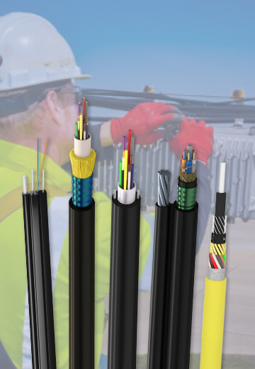
Fiber optic cable systems
Outdoor, indoor, FTTH and distribution cable lines for access networks, backbone routes and campus deployments.
 Telecom & ISP NetworksFTTH, PON, ODN
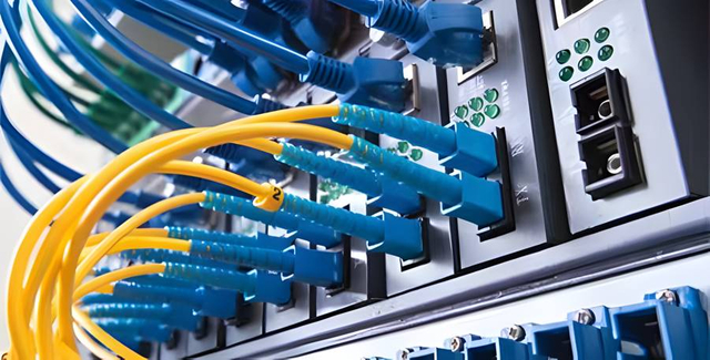 Data Center InfrastructureServer room cabling
 Building Low-Voltage SystemsBMS, AV, weak current
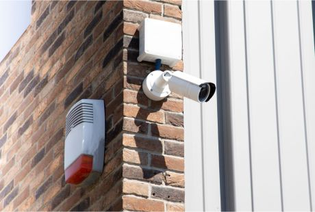 Security & Fire ProtectionAlarm, CCTV, access
 Industrial Automation CablePLC, RS485, fieldbus
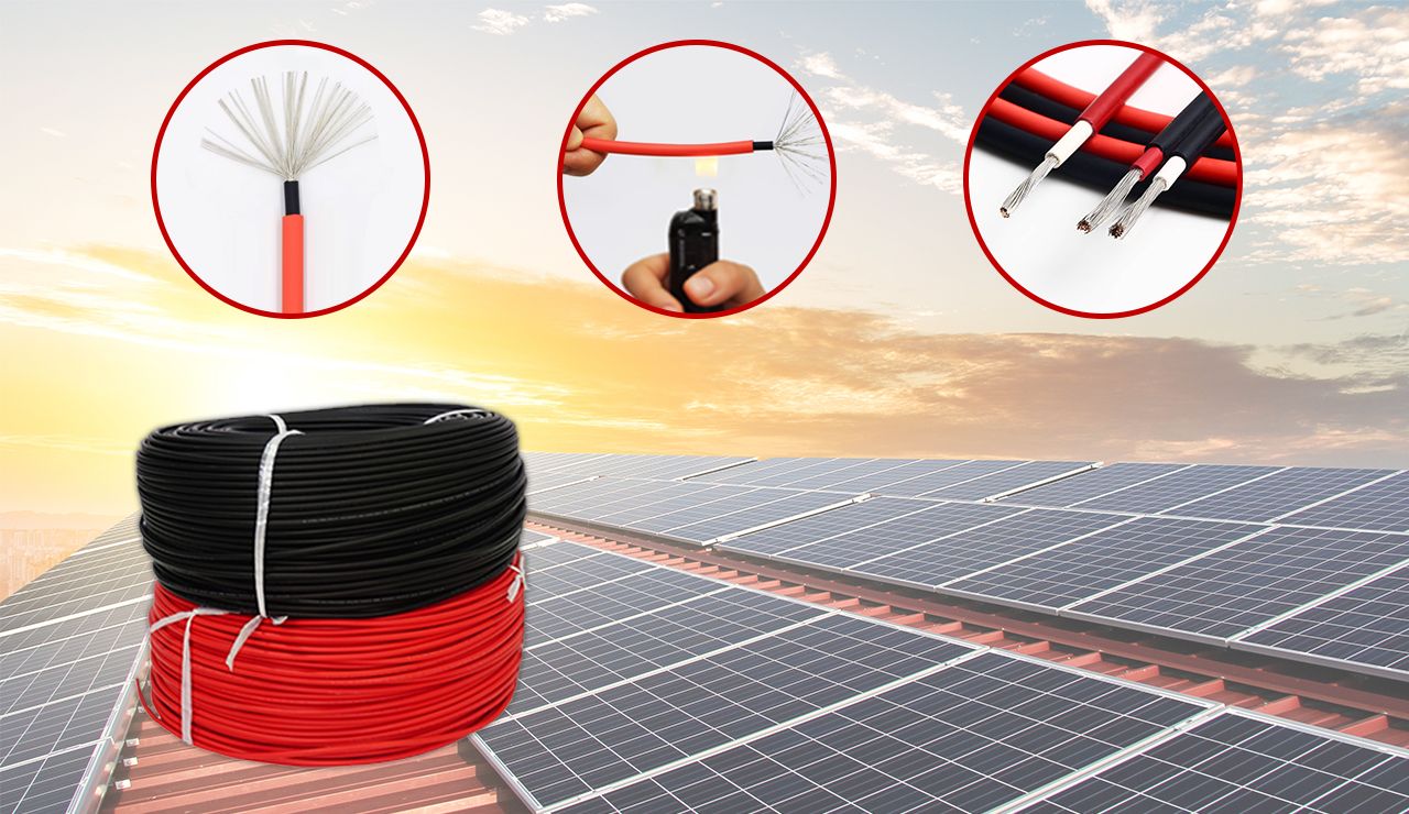 Energy & Power InfrastructureSolar, battery, power
Telecom & ISP Networks
For FTTH / PON access, outdoor fiber deployment, aerial routes, duct routes, direct burial routes, rural broadband and ODN planning.
Tools
Use calculators and planning tools for conduit capacity, PoE voltage drop and fiber optic link loss budget work.