Comprehensive Guide to Fiber Optic Patch Cables
Author: James Publish Time: 12-08-2021 Origin: Site
Fiber Optic Patch Cable Guide: Types, Connectors and Selection A practical guide to choosing fiber type, connector, end-face polish, polarity, cable construction, jacket rating, length and bend performance for a reliable optical link. |
A fiber optic patch cable—also called a fiber patch cord or patch lead—is a factory-terminated optical cable with connectors on both ends. It connects transceivers, patch panels, optical distribution frames, media converters, test equipment and other fiber interfaces. The correct assembly must match the ports at both ends and the optical requirements of the complete link.
The cable label alone does not determine link speed or reach. Those depend on the transceivers, wavelength, fiber category, connector loss, splice loss, link length and the applicable interface standard. Use this guide to define the patch cable, then confirm the final link budget and equipment compatibility.

■ What Is a Fiber Optic Patch Cable?
Patch cables are short, connectorized assemblies used to complete accessible connections within a fiber cabling system. Common examples include equipment-to-patch-panel links, rack-to-rack cross-connects, connections inside telecom rooms and short runs between optical devices. They are available as simplex, duplex and multifiber assemblies, with indoor, armored, outdoor or other application-specific constructions.
A complete patch-cable description normally includes: Connector at end A + connector at end B + polish + fiber category + fiber count/polarity + cable diameter or construction + jacket rating + length. |
■ Choose the Fiber Category First
Match the patch cable to the installed cabling and the optical interface. Single-mode and multimode fiber are not interchangeable choices, and multimode categories should not be treated as identical merely because they share a 125 µm cladding diameter.
| Fiber category | Typical role | Selection note |
| OS1 / OS2 single-mode | Telecom, PON, campus and data-center links using single-mode optics | Match the transceiver wavelength, interface and installed single-mode plant; OS2 is commonly specified for new outside-plant and indoor single-mode links. |
| OM1 / OM2 multimode | Legacy premises networks | Confirm the exact transceiver and permitted reach. Some legacy laser-based interfaces require a mode-conditioning patch cord. |
| OM3 / OM4 multimode | Short-reach Ethernet and data-center links | Use the interface specification—not jacket color alone—to confirm speed and maximum channel length. |
| OM5 multimode | Wideband multimode applications | Specify only when the optical design or project standard requires OM5; it is not a universal upgrade for every multimode link. |

■ Connector Types and Where They Are Used
The connector must physically match the adapter or equipment port at each end. Hybrid assemblies such as LC-to-SC are normal when the two interfaces differ. The most common choices are listed below; specialized hardened, expanded-beam and small-form-factor connectors should be selected against the exact equipment and environmental specification.
| Connector | Key characteristic | Common applications |
| LC | Compact connector with a 1.25 mm ferrule | SFP-family transceivers, high-density panels and equipment ports |
| SC | Push-pull connector with a 2.5 mm ferrule | ODFs, PON equipment, media converters and premises cabling |
| FC | Threaded coupling | Test equipment, laboratories and selected telecom systems |
| ST | Bayonet coupling | Legacy premises and industrial installations |
| MPO | Multifiber interface whose fiber count, key orientation and pin configuration must be defined | Parallel-optics links, trunks and high-density breakout systems |
■ UPC vs APC: Match the End-Face Polish
UPC and APC describe different physical-contact end-face geometries. UPC uses a polished curved end face, while APC uses an angled end face to reduce reflected power in reflection-sensitive systems. APC connectors are commonly identified by green bodies, but the label and equipment documentation remain the authoritative checks.
Do not mate UPC and APC connectors. Their different end-face geometries can create an air gap, high loss, excessive reflection and possible end-face damage. Match the connector polish at the equipment, adapter and patch cable. |
■ Simplex, Duplex and Multifiber Polarity
Simplex means one fiber path. It is often used with bidirectional single-fiber optics, monitoring links and other interfaces designed for one fiber. It does not mean that the system can communicate in only one direction; the transceiver design determines how signals are carried.
Duplex uses two fibers, typically one for transmit and one for receive. The two ends must maintain the polarity required by the equipment so that the transmitter on one side reaches the receiver on the other.
Multifiber assemblies require more information: fiber count, key orientation, male or female pin configuration, polarity method and breakout mapping. Do not order an MPO assembly from fiber count and length alone.

■ Cable Construction and Jacket Selection
The connector and fiber may be correct while the cable construction is wrong for the route. Confirm whether the assembly will remain inside a rack, pass through a building pathway, enter an outdoor enclosure, face frequent handling or require additional mechanical protection.
| Construction | Where it fits | What to confirm |
| Standard indoor | Protected racks, cabinets and telecom rooms | Jacket rating, cable diameter, pathway rules and expected handling |
| Armored | Routes needing additional crush or animal-damage resistance | Armor type, minimum bend radius, grounding requirements if applicable and termination compatibility |
| Bend-insensitive | Dense routing and access-network installations | Exact G.657 category and the completed cable manufacturer's bend specification |
| Outdoor / hardened | Outdoor cabinets, antennas, FTTA/FTTH and exposed routes | Ingress protection, UV exposure, temperature, pulling load and exact hardened connector interface |
| Mode-conditioning | Specific legacy laser-based interfaces over legacy multimode fiber | Transceiver vendor instructions, fiber category, link length and installation orientation |
 |  |  |
Jacket ratings and colors
PVC and LSZH describe material or smoke/halogen characteristics, while OFNR and OFNP are North American pathway fire ratings for nonconductive optical-fiber cable. These terms are not interchangeable. Specify the rating required by the building code, project specification and installation pathway.
Jacket color is a useful identification aid—yellow is widely associated with single-mode, orange with OM1/OM2, aqua with OM3/OM4 and lime green with OM5—but color alone does not prove fiber category, performance or compliance. Read the cable print and product documentation before installation.
■ Length, Diameter and Minimum Bend Radius
Choose enough length for the intended routing, service loop and strain relief without leaving excessive slack in a congested cabinet. Cable diameter affects flexibility, protection and routing density, but it does not by itself define the allowable bend radius.
The old rule-of-thumb table has been removed because a single diameter-based multiplier cannot represent every patch-cable construction. Minimum bend radius can differ between installation and long-term static use, and it depends on the fiber, buffer, strength members, armor and jacket. Follow the completed cable manufacturer's datasheet.
ITU-T G.657 fiber is designed for improved macrobending performance compared with conventional G.652 fiber, but “bend-insensitive” does not mean loss-free at any bend. The cable construction and installation method still control the finished assembly's allowable bend and long-term reliability.
■ How to Read a Patch Cable Name
A clear product name should let the buyer reconstruct the assembly. For example, LC/UPC to SC/UPC duplex OS2, 2.0 mm, LSZH, 5 m defines both connectors and polishes, the fiber category, fiber count, cable diameter, jacket material and length. For MPO or other multifiber assemblies, add fiber count, pin configuration, key orientation and polarity method.

■ Inspection, Cleaning and Link Verification
Contamination and damaged end faces are common causes of avoidable optical loss. Keep dust caps on unused connectors, but do not assume a capped connector is clean. Inspect and clean connector end faces with procedures and tools suitable for the connector type before mating, especially after a connector has been handled or exposed.
Confirm connector type, polish and adapter compatibility before insertion.
Route the cable without tension, pinching, sharp bends or pressure from cabinet doors.
Verify duplex polarity or multifiber mapping before service activation.
Measure loss using the project's accepted test method and reference procedure; acceptance limits belong to the complete link specification.
■ Fiber Patch Cable Selection Checklist
Before requesting a quotation or releasing a purchase order, record the following information:
Equipment interfaces: connector and polish at end A and end B.
Optical interface: transceiver type, wavelength and required fiber category.
Fiber count and polarity: simplex, duplex or multifiber mapping.
Length and routing: measured route, service loop, cabinet density and bend constraints.
Environment: indoor pathway, plenum/riser requirement, outdoor exposure, temperature, moisture, chemicals or mechanical risk.
Construction: cable diameter, LSZH/PVC or pathway rating, armor, breakout, hardened interface or other protection.
Quality documentation: required inspection, insertion-loss/return-loss test data, labeling and packaging.
ZION's current fiber optic patch cord range can be reviewed when matching connector, fiber, jacket and construction options to a project specification.
■ Frequently Asked Questions
Can I connect an APC patch cable to a UPC adapter or port?
No. Match APC to APC and UPC to UPC. The different end-face geometries should not be mated.
Does a yellow or aqua jacket guarantee the fiber type?
No. Color is an identification convention, not proof of performance. Confirm the cable print, product label and technical documentation.
Is a simplex cable only for one-way communication?
No. Simplex describes one fiber path. Bidirectional optics can transmit and receive over the same fiber using different wavelengths; compatibility depends on the paired transceivers.
Can I calculate bend radius from the patch-cable diameter?
Not reliably. Diameter-based rules can be useful during preliminary planning, but the finished cable construction determines the specified installation and long-term bend radii. Use the manufacturer's datasheet.
When is a mode-conditioning patch cord required?
It is used only with specified laser-based interfaces over particular legacy multimode links. Follow the transceiver manufacturer's compatibility and installation instructions; do not use it as a general replacement for an ordinary multimode patch cable.
■ Conclusion
A reliable fiber patch cable starts with complete interface information, not a generic connector name. Match the fiber category to the optics and installed plant, match the connector and polish at both ends, define polarity, choose a construction and jacket for the route, and follow the finished cable's bend and handling limits. Inspection, cleaning and link-level testing then confirm that the installed connection meets the project requirement.



 Fiber Optic Tools
Products 6 families
Solutions 6 markets
Resources Tools & docs
Certificate
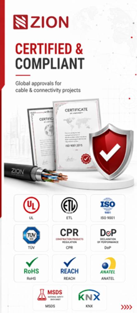
Certification and compliance references for project review, qualification and purchasing documentation.
 Fiber Optic CableAccess and backbone
 Ethernet CableCat5e to Cat8
 Coaxial CableRF and video signal
 Fire, Security & AlarmSafety systems
 Voice, Audio & VideoSignal cabling
 Power & Control CableEnergy and control
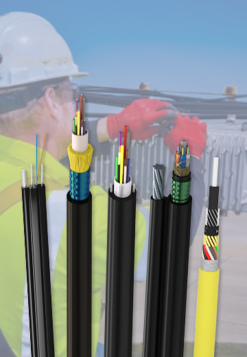
Fiber optic cable systems
Outdoor, indoor, FTTH and distribution cable lines for access networks, backbone routes and campus deployments.
 Telecom & ISP NetworksFTTH, PON, ODN
 Data Center InfrastructureServer room cabling
 Building Low-Voltage SystemsBMS, AV, weak current
 Security & Fire ProtectionAlarm, CCTV, access
 Industrial Automation CablePLC, RS485, fieldbus
 Energy & Power InfrastructureSolar, battery, power
Telecom & ISP Networks
For FTTH / PON access, outdoor fiber deployment, aerial routes, duct routes, direct burial routes, rural broadband and ODN planning.
Tools
Use calculators and planning tools for conduit capacity, PoE voltage drop and fiber optic link loss budget work.