FTTH Installation Process: From Fiber Cabling to System Handover
Author: Isaac Publish Time: 26-02-2025 Origin: Site
FTTH Installation Process: From Cabling to Handover A controlled workflow for placing the subscriber drop, completing optical connections, activating the ONT, testing the service, and delivering traceable records.
Fiber to the home (FTTH) extends an optical access network to a residence or business premises. A typical installation connects an operator-approved distribution point to the subscriber through drop cable, terminals or outlets, optical connectors or splices, an optical network terminal (ONT), and the customer-side Ethernet or Wi-Fi network. The work is complete only when the physical route, optical performance, device registration, service operation, labels, and handover records all meet the project requirements.
The sequence below is a project workflow, not a substitute for the operator's method statement. Cable construction, connector polish, splitter architecture, test wavelengths, acceptance limits, and ONT provisioning method must already be approved before field work starts.
1. Confirm the Network Path and Work Package
Start with the approved ODN drawing, work order, port allocation, cable schedule, optical budget, safety plan, and acceptance requirements. A subscriber path may run from a fiber access terminal or distribution box through a drop cable to an outlet and ONT. The exact sequence varies with centralized or cascaded splitting, building type, pre-terminated or field-terminated drops, and the operator's demarcation point. ZION's FTTH/PON access network solution provides a component-level view of this passive path.
Verify the serving terminal, splitter output, port identifier, intended premises, route, cable type, fiber assignment, and reserve-length rule.
Confirm SC/APC, SC/UPC, LC/UPC, or another approved interface at every connection; APC and UPC must not be mated together.
Identify whether fibers are dark or live and whether any existing customer or network service may be affected.
Confirm permits, building access, customer appointment, outage window, drilling approval, working-at-height controls, and restoration responsibilities.
Record the approved test method, wavelengths, reference method, pass/fail limits, naming convention, and required handover format.
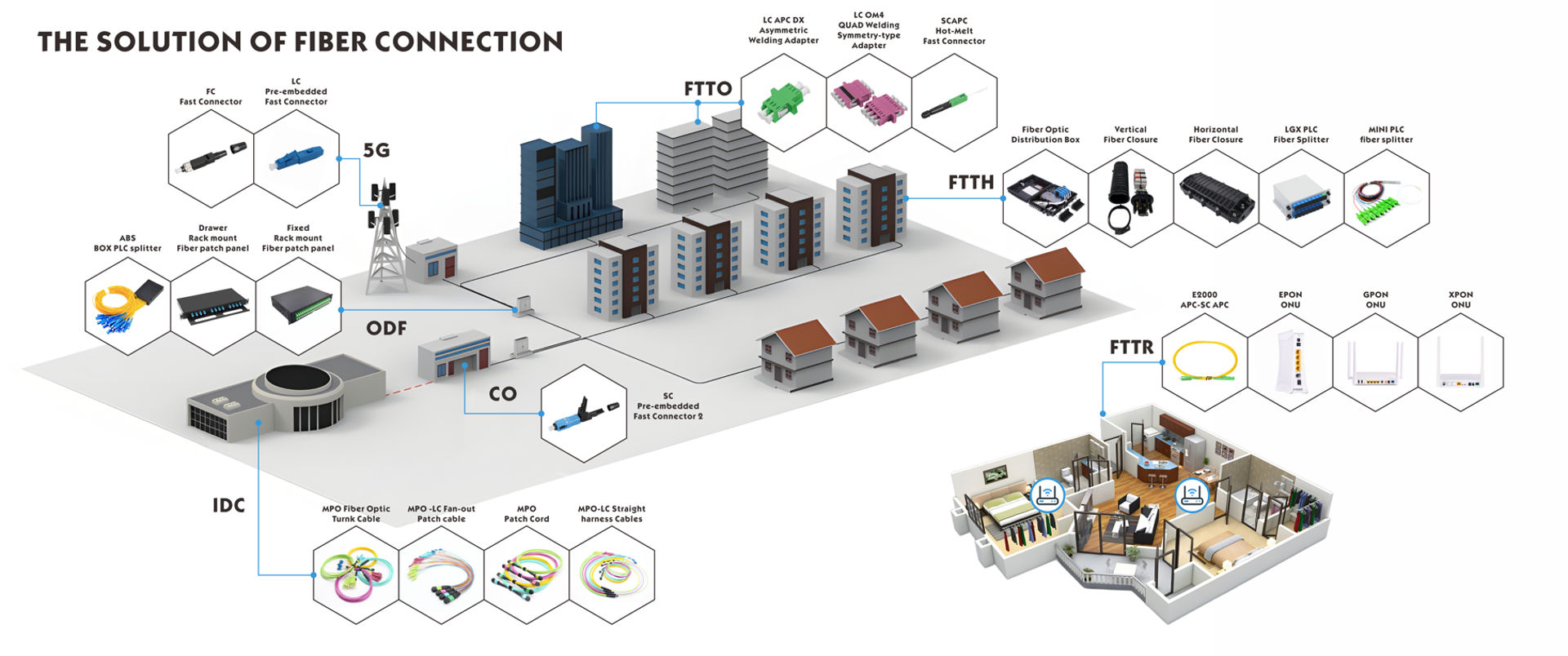
2. Prepare the Route and Place the Drop Cable
Walk the route before pulling. Confirm pathway condition, surface or concealed mounting method, entry point, penetrations, access points, cable-support spacing, service-loop locations, and the final ONT position. Use cable, conduit, closures, entry seals, and firestopping materials rated for the actual indoor, outdoor, aerial, duct, moisture, UV, and building-code conditions.
Inspect the cable and pathway. Check packaging, reel or coil condition, cable markings, route obstructions, sharp edges, water paths, and required pulling or blowing equipment.
Control payout and pulling. Feed cable from the approved direction, prevent twist and kinks, and use pulling hardware or lubrication only when compatible with the cable and pathway.
Protect mechanical limits. Do not exceed the cable manufacturer's maximum pulling tension, crush load, or minimum bend radius during installation or after placement.
Support without deformation. Use approved clamps, hook-and-loop ties, brackets, conduit, or trays. Avoid overtightened cable ties and fasteners that compress the jacket.
Provide controlled reserve. Store service loops at approved locations and diameters so they remain accessible for termination or future repair.
Seal and restore. Protect cable entries, reinstate fire and weather barriers, close enclosures, remove debris, and update the route if field conditions required a change.
Glass fiber is not degraded by electromagnetic interference in the way copper communication cable is. Route separation from electrical services may still be required for worker safety, shared-pathway rules, fire and building codes, access, mechanical protection, and conductive armor or strength members. Follow the approved design and local requirements rather than claiming that fiber will suffer electrical crosstalk.
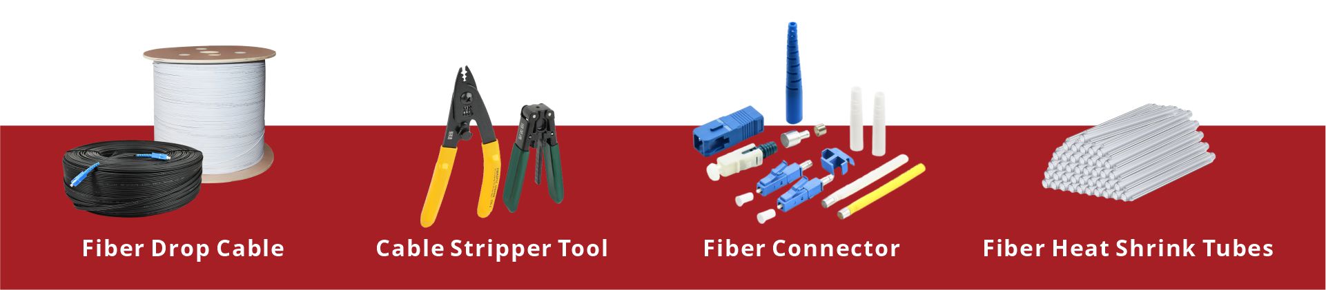
3. Install Terminals, Outlets, and Cable Management
Mount fiber access terminals, distribution boxes, customer outlets, splice trays, adapters, and patching hardware at the locations shown on the approved drawing. Each enclosure must match the cable-entry range, port capacity, splitter or splice arrangement, environmental exposure, mounting surface, and service-access requirements.
Use the specified anchors, brackets, clamps, entry glands, seals, and strain-relief parts.
Keep fiber routing within tray and enclosure bend limits; prevent fibers from crossing hinges, screw points, sealing surfaces, and sharp edges.
Separate working fibers, spare fibers, splitters, adapters, and splice protectors according to the approved layout.
Label the enclosure, input cable, output ports, fiber or tube assignment, and subscriber destination before closing the housing.
Bond or ground conductive cable members and metallic hardware where the design and applicable rules require it.
4. Splice or Terminate the Optical Fiber
Complete the connection using the termination method approved for the network and cable. Fusion splicing typically uses a prepared pigtail or joins cable fibers, while field-installable connectors and mechanical splices use their own cable-preparation dimensions, assembly fixtures, and acceptance checks. A factory-terminated drop may avoid field termination but still requires controlled pulling, connector protection, inspection, and correct routing.
Create a clean work area and protect open connectors, adapters, tools, and prepared fibers from dust and moisture.
Prepare the jacket, strength members, buffer, and coating with tools matched to the cable construction.
For fusion splicing, clean and precision-cleave the fiber, select the correct holder and program, evaluate the splice, apply the approved protection sleeve, and place the splice in the tray without stress.
For a field connector or mechanical splice, follow its manufacturer-specified strip and cleave lengths, assembly sequence, fiber type, and visual or optical verification method.
Collect bare-fiber offcuts immediately in a closed sharps container and keep food and drink away from the work area.
A current example of a field splicing platform is the ZCFFSAI-20 fusion splicer. Selection still depends on the approved fiber, holders, splice method, environmental range, accessories, service support, and project acceptance process.

5. Inspect, Clean, and Complete Optical Connections
Before mating any connector, identify whether the circuit is live and apply the operator's optical-safety procedure. Never look into a fiber, connector, adapter, or instrument port. Use a video inspection probe with the correct tip to inspect both sides of each connection, clean only with approved fiber-cleaning tools and materials when necessary, and reinspect before mating.
Inspect patch cords, pigtails, field connectors, adapter bulkheads, splitter leads, ONT ports, and test reference cords.
Use connector-specific one-click cleaners, lint-free wipes, swabs, and approved solvent according to the cleaning procedure.
Do not assume a dust cap means the end face is clean, and do not reuse contaminated wipes or swabs.
Confirm the correct adapter and polish before connection; never force a connector into an incompatible interface.
Install patch cords with strain relief, protected bend radius, clear labels, and no pressure from enclosure covers.
6. Install and Activate the ONT
Mount the ONT in the approved dry, ventilated, serviceable location, protected from impact, heat, moisture, and unauthorized handling. Confirm the correct power adapter, outlet, cable slack, optical connector, Ethernet interface, and customer equipment. The router or Wi-Fi access point position should support the agreed indoor coverage and cabling plan; a convenient fiber entry point is not automatically the best Wi-Fi location.
Register and provision the ONT using the operator-authorized method. In PON systems this may involve serial number or credential registration, an OLT management platform, OMCI, and an approved service profile. Do not invent IP, VLAN, voice, multicast, or authentication settings at the premises. Record the ONT identifier, serving OLT/PON/port data, service template reference, firmware state when required, and any configuration change allowed by the operator.
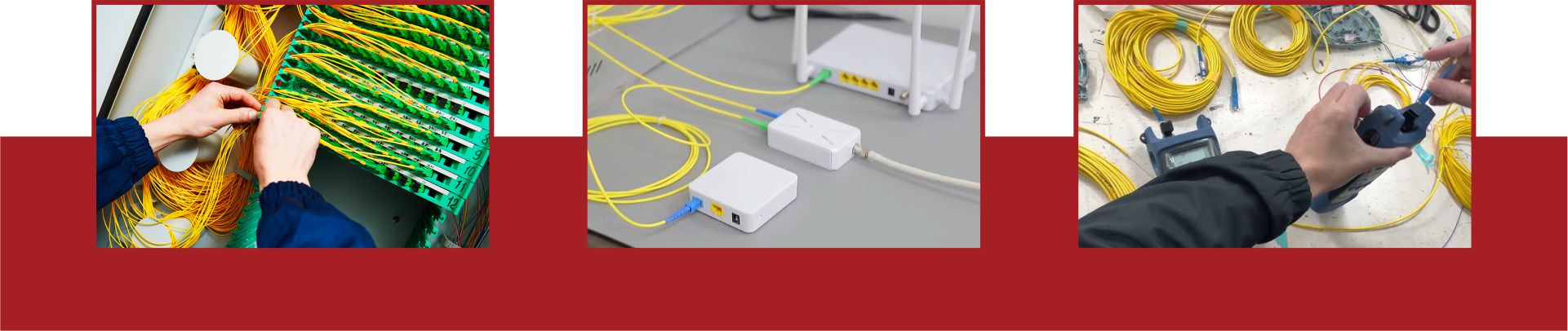
7. Test the Passive Link and Active Service
Follow the approved test plan and keep passive optical acceptance separate from active service verification. A useful sequence is inspection, continuity or identification, end-to-end loss or PON power measurement, event analysis when required, ONT registration, and then service tests.
Passive optical checks
Verify continuity, route, fiber assignment, and any required polarity or endpoint identification.
Measure end-to-end insertion loss with a compatible light source and power meter or OLTS when the acceptance method requires it.
Measure wavelength-selective PON power with a suitable PON meter when activating or troubleshooting a live network.
Use an OTDR with appropriate launch/receive fibers, wavelengths, ranges, pulse widths, and interpretation when event location, splice assessment, route length, or fault analysis is required.
Compare results with the designed optical budget and signed acceptance limits, not a universal dB number copied from another network.
Active service checks
Confirm ONT registration, expected status indicators, management visibility, and the assigned service profile.
Verify Ethernet link negotiation and the operation of subscribed internet, voice, television, or business services that are in scope.
Run throughput and latency tests using the operator-approved server, wired test device, interface, and method; record whether Wi-Fi is included or excluded.
Check customer-side router, Ethernet cabling, Wi-Fi placement, and device limits before attributing a poor application result to the optical link.
The FTTH drop-cable testing and acceptance guide offers additional testing context. The project design, operator method, instrument instructions, and signed acceptance plan remain authoritative for the installed network.
8. Resolve Exceptions Before Closing the Work
If a result fails, preserve the original reading and diagnose the failure systematically. Repeating a test without controlling the setup can hide the cause or create an untraceable acceptance record.
Verify the test limit, wavelength, reference method, adapters, launch/receive cords, and instrument configuration.
Inspect test cords, bulkheads, splitters, patch cords, and equipment ports; clean and reinspect where required.
Check routing, tight bends, crushed cable, strained connectors, incorrect patching, wrong port assignment, and unprotected splices.
Use OTDR or another approved diagnostic method to locate an event when the link length and network state make that method suitable.
Repair, reterminate, resplice, reroute, or replace the affected item under the approved procedure.
Retest the affected element and the complete required path, then record the final result and corrective action.
9. Complete Acceptance and System Handover
A handover package should allow another technician to identify the route, reproduce the acceptance decision, restore service, and distinguish the operator network from customer equipment. Compile only records required by the project, but keep them complete and internally consistent.
As-built route and any approved deviation from the original drawing.
Serving terminal, splitter, port, cable, fiber, outlet, ONT, router, and customer identifiers as applicable.
Connector types, splice locations, enclosure layout, labels, photographs, and reserve-fiber information.
End-face inspection records, insertion-loss or PON power results, OTDR traces when required, active-service results, and instrument/reference details.
ONT registration or service-profile reference, serial number, power arrangement, and allowed configuration record.
Outstanding exceptions, approved concessions, restoration actions, customer equipment limitations, and maintenance contacts.
During customer handover, explain the ONT and router indicators, approved power-cycle procedure, Wi-Fi limitations, equipment ventilation, cable protection, fault-reporting channel, and which equipment the customer must not disconnect or relocate. Obtain the required customer or supervisor sign-off only after the agreed tests and records are complete.
Frequently Asked Questions
What is the correct order for an FTTH installation?
A typical order is scope and route confirmation, pathway preparation, drop-cable placement, terminal installation, splicing or termination, inspection and cleaning, ONT installation and registration, passive optical testing, active service testing, corrective work, documentation, and handover. The approved operator procedure decides the exact sequence.
Does fiber need separation from power cable because of EMI?
Glass optical fiber is immune to EMI, so the reason is not copper-like crosstalk. Separation or a specific pathway may still be required for electrical safety, access, building and fire rules, shared-conduit restrictions, mechanical protection, and conductive cable members. Follow the approved design and local requirements.
Can an OTDR alone certify an FTTH link?
Not automatically. An OTDR provides event and location information through an indirect backscatter measurement. End-to-end insertion loss, live PON power, end-face inspection, ONT registration, and service tests may also be required. Use the signed acceptance plan.
Should the installer manually configure the ONT VLAN and IP settings?
Only when the operator's authorized procedure requires it. Many PON deployments use OLT-side registration, OMCI, and predefined service profiles. Unauthorized local changes can prevent registration or create an undocumented service mismatch.
When is the FTTH installation ready for handover?
It is ready when the installed route and interfaces match the approved work, required optical and service tests pass, exceptions are resolved or formally accepted, labels and as-built records are complete, the customer instructions are delivered, and the required sign-off is recorded.
Conclusion
An FTTH installation succeeds through controlled transitions: from design to route, route to cable placement, cable to protected optical connections, passive link to registered ONT, test results to corrective action, and completed work to traceable handover. Keeping those transitions aligned with the network design and acceptance plan is more reliable than treating cabling, device activation, testing, and documentation as separate tasks.



 Fiber Optic Tools
Products 6 families
Solutions 6 markets
Resources Tools & docs
Certificate
Certification and compliance references for project review, qualification and purchasing documentation.

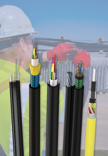 Fiber Optic CableAccess and backbone
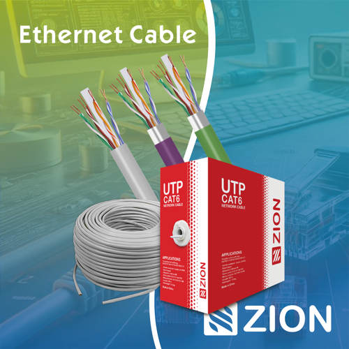 Ethernet CableCat5e to Cat8
 Coaxial CableRF and video signal
 Fire, Security & AlarmSafety systems
 Voice, Audio & VideoSignal cabling
 Power & Control CableEnergy and control
Fiber optic cable systems
Outdoor, indoor, FTTH and distribution cable lines for access networks, backbone routes and campus deployments.
 Telecom & ISP NetworksFTTH, PON, ODN
 Data Center InfrastructureServer room cabling
 Building Low-Voltage SystemsBMS, AV, weak current
 Security & Fire ProtectionAlarm, CCTV, access
 Industrial Automation CablePLC, RS485, fieldbus
 Energy & Power InfrastructureSolar, battery, power
Telecom & ISP Networks
For FTTH / PON access, outdoor fiber deployment, aerial routes, duct routes, direct burial routes, rural broadband and ODN planning.
Tools
Use calculators and planning tools for conduit capacity, PoE voltage drop and fiber optic link loss budget work.