01 PH120 
Fire Resistant Cable
UL EN 50200 PH120 Solid Fire Cable
For fire alarm and emergency routes where PH120 circuit integrity and solid conductor construction are requested.
PH120 Solid Fire Rated
View Product → 
ZION helps contractors, distributors and system integrators prepare quote-ready fire alarm cable BOMs for addressable detector loops, notification appliance circuits, smoke-extraction controls, emergency lighting, voice evacuation, riser shafts, plenum spaces and fire-resistant emergency routes. Select by circuit function, voltage drop, fire alarm circuit distance, conductor size, shielding, route rating and required fire performance before comparing price.
Fire alarm cable selection should start from circuit function, route type, circuit distance, connected load and required fire performance. Separate addressable loops, notification appliance circuits, smoke-extraction controls, emergency lighting, voice evacuation, riser/plenum pathways and fire-resistant emergency routes. Then verify voltage drop and panel compatibility before choosing PH120, BS 6387 CWZ, FPLP, FPLR, shielded or unshielded cable.
For a B2B project buyer, the useful answer is how to convert drawings and circuit schedules into cable families. The page should separate initiating device circuits, notification appliance circuits, voice evacuation routes, control interfaces, riser/plenum pathways and fire-resistant critical circuits. This makes the content more direct, more professional and easier to use for RFQ and BOM preparation.
Explain where each cable is used, not only cable names and marketing claims.
Show which parameters must be confirmed before quotation and approval.
Use route rating, fire performance, conductor size and shielding as selection logic.
Keep claims document-based: datasheet, sample, marking, packing and certificate review.
| BOM Area | Typical Devices | Cable Direction | Information to Confirm |
|---|---|---|---|
| Initiating device circuit | Smoke detector, heat detector, manual call point, input module | Shielded or unshielded fire alarm cable according to panel and route condition | Conductor size, pair/core count, panel wiring method, loop length and color. |
| Notification appliance circuit | Horn, strobe, bell, sounder, speaker-strobe | Fire alarm cable selected by load current, distance and voltage drop check | Device count, route length, current load, conductor size and spare percentage. |
| Voice evacuation route | Speaker line, amplifier route, emergency communication circuit | Fire-rated or shielded cable where required by system design | Impedance, survivability requirement, route grouping and termination method. |
| Control and interface wiring | Relay module, damper, elevator interface, sprinkler monitor | Multi-core or paired fire alarm/control cable with clear identification | Terminal schedule, cable marking, conductor count and cable color. |
| Plenum and riser pathways | Ceiling air-handling spaces and vertical shafts between floors | FPLP/plenum or FPLR/riser fire alarm cable according to project route | Pathway type, local requirement, shield preference and packing length. |
| Critical circuit integrity route | Emergency control, evacuation, backbone or protected fire safety route | PH120, BS 6387 CWZ, E30/E90 or specified fire-resistant cable | Exact standard wording, certificate expectation, conductor type and installation method. |
| Selection Point | Decision Logic | Why It Matters | What ZION Needs |
|---|---|---|---|
| Circuit function | Separate detection, notification, speaker, control and backbone circuits. | Different circuits may require different conductor sizes, shielding or fire ratings. | Circuit schedule, device list and drawing notes. |
| Route type | Identify conduit, tray, ceiling space, riser shaft, plenum space or protected route. | Route type decides whether plenum, riser, LSZH or fire-resistant cable is needed. | Installation location and local project requirement. |
| Fire performance | Confirm PH120, BS 6387 CWZ, E30/E90, FPLP, FPLR or other wording exactly. | Similar cable descriptions may not be accepted during project submittal. | Specification clause, certificate request and marking requirement. |
| Conductor size | Select size by load, distance, voltage drop and termination requirement. | Notification circuits and long routes can fail if conductors are under-sized. | Length, load, conductor size preference and packing length. |
| Shielding | Use shielded cable when the panel, route length or interference environment requires it. | Shielding and grounding should match panel practice to avoid signal problems. | Shield type, drain wire request and grounding method. |
| Documentation | Prepare datasheet, sample, marking, packing and certificate discussion before order. | Document mismatch can delay approval even when the cable construction is correct. | Target market, approval requirement and submittal deadline. |
| Application | Practical Cable Direction | Engineering Checks | RFQ Inputs |
|---|---|---|---|
| Addressable fire alarm loop cable | Use the panel manufacturer's approved pair/core construction; twisted, shielded or unshielded designs depend on the panel and interference environment. | Loop resistance, capacitance, inductance, topology, isolators, shield termination and maximum panel-rated length. | Panel/model, device count, one-way loop length, AWG, shield and route rating. |
| Notification appliance cable | Choose fire alarm cable with conductor size determined by worst-case alarm current and voltage drop, not device count alone. | Supply tolerance, synchronized appliance current, last-device minimum voltage, branch layout and design margin. | Voltage, appliance schedule, current per device, route lengths and required fire rating. |
| Smoke extraction cable | Use the control or power cable specified for fans, dampers and control interfaces; where operation during fire is required, select a fire-resistant circuit-integrity construction and protected installation system. | Control versus motor power, load, voltage, fire-survival duration, mechanical protection and local approval. | Equipment load, control diagram, route, conductor count/size and PH/CWZ or other specified classification. |
| Emergency lighting cable | Use cable accepted for the emergency-lighting circuit and route. Central-battery or maintained systems may require fire-resistant power cable; self-contained luminaires may follow a different local wiring method. | System architecture, voltage, load, protective device, voltage drop, circuit integrity and local electrical/fire code. | Central or self-contained system, load schedule, route length, conductor size and required survival period. |
| Voice evacuation cable | Use speaker or emergency communication cable matching amplifier output and the project's pathway and survivability requirements; shield or fire-resistant construction is selected only when specified. | 70/100 V or other system, speaker tap load, impedance, voltage drop, segregation, survivability and amplifier listing. | Amplifier model, speaker schedule, route length, conductor size, shield and fire rating. |
There is no universal AWG. Start with the panel's permitted wire range and maximum loop resistance, calculate the complete out-and-back conductor resistance, then check capacitance and device count. If 18 AWG exceeds the panel limit, evaluate 16 AWG or 14 AWG only if the terminals, listing and project specification permit it. The approved panel data—not length alone—sets the final addressable fire alarm loop cable size.
Use the cable manufacturer's maximum DC resistance at the relevant conductor temperature, not only a nominal AWG table.
Use worst-case alarm load, including synchronized or peak appliance values required by the equipment instructions.
Record whether a stated length is one-way route length, loop perimeter or total conductor length to avoid a two-times error.
Confirm the selected cable and installation method against the equipment listing, project specification and locally adopted code.
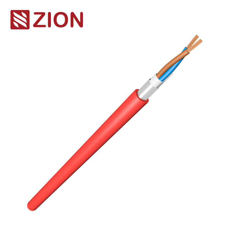
For fire alarm and emergency routes where PH120 circuit integrity and solid conductor construction are requested.
For protected fire safety routes where CWZ fire, water and mechanical shock performance is specified.
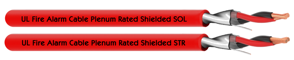
For air-handling ceiling spaces and plenum routes where shielding and plenum cable marking are required.
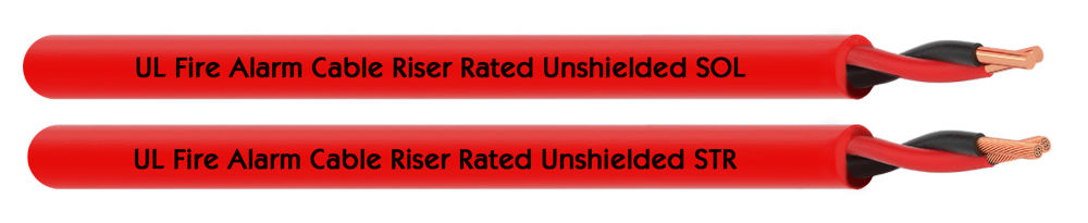
For vertical building shafts and floor-to-floor fire alarm routes where unshielded FPLR construction is accepted.
| ZION Product Family | Typical Project Use | Selection Strength | Buyer Check Before RFQ |
|---|---|---|---|
| PH120 fire cable | Fire alarm and emergency circuits requiring EN 50200 style circuit integrity. | Circuit integrity | PH class, conductor type, cable marking, certificate request and installation method. |
| BS 6387 CWZ fire cable | Critical fire safety routes requiring fire, water and mechanical shock performance. | Critical route | CWZ wording, flexible/solid conductor, sheath type, test document expectation. |
| Plenum fire alarm cable | Air-handling spaces, ceiling voids and plenum pathways in building projects. | Pathway rating | Shielded/unshielded construction, jacket marking, color and packing length. |
| Riser fire alarm cable | Vertical building shafts and floor-to-floor routes. | Vertical route | Floor count, route length, conductor size and circuit grouping. |
| Shielded fire alarm cable | Long signal routes or electrically noisy low-voltage pathways. | Noise control | Shield/drain requirement, grounding method and panel compatibility. |
| Unshielded fire alarm cable | Standard device circuits where shielding is not required by system design. | Cost-effective routing | Panel acceptance, route environment and conductor size. |
Provide panel type, device list, route drawing, circuit category and any standard or certificate wording in the project specification.
Group PH120, CWZ, plenum, riser, shielded and unshielded items so quotation does not mix different approval requirements.
Check quantity, packing length, cable color, private label marking, sample request and document expectations before order confirmation.
Voltage drop lowers the voltage available at horns, strobes, bells and speaker-strobes. If the last appliance receives less than its listed minimum operating voltage under worst-case alarm load, output or synchronization may be unreliable. Size notification appliance cable from panel output tolerance, total alarm current, conductor resistance, route layout and the minimum device voltage, with the project's required design margin.
No single AWG fits every long loop. Check the panel's allowed conductor range, maximum loop resistance/capacitance, topology and device load. Calculate round-trip resistance using the cable datasheet. If 18 AWG is outside the panel limit, consider 16 or 14 AWG only when panel terminals, listing and specifications allow it.
A smoke extraction cable must match the fan, damper or control-interface circuit. If the circuit must operate during a fire, use the specified fire-resistant circuit-integrity cable and approved support system, such as the project-required PH120, CWZ or equivalent classification. Confirm voltage, load, cores, survival period and local approval.
Use emergency lighting cable accepted for the system architecture and route. Central-battery and maintained circuits may require fire-resistant power cable, while self-contained luminaires can have different wiring rules. Confirm voltage, load, protective device, voltage drop, circuit-integrity period and locally adopted requirements.
Voice evacuation systems need speaker or emergency communication cable compatible with the amplifier output, speaker load and pathway. Conductor size follows impedance and voltage-drop calculations; shielding, fire resistance and survivability follow the equipment instructions and project code. Do not assume ordinary detector-loop cable is suitable.
For a two-conductor circuit with the load treated at the endpoint, use Vdrop = 2 × one-way length × alarm current × conductor resistance per unit length. For distributed appliances, calculate each segment using its downstream current and add the segment drops. Compare the result with panel minimum output minus the last device's minimum voltage, then apply the specified margin.
Use the addressable fire alarm loop cable construction approved by the panel manufacturer. Pair/core count, twist, shield, capacitance, inductance and resistance must remain within the panel data. Route rating, fire performance and shield grounding are then selected for the installation environment and specification.
Voltage drop is proportional to resistance, current and distance. Higher alarm current or a longer route produces more drop; a larger copper conductor lowers resistance and can extend fire alarm circuit distance. Temperature also raises copper resistance, so use the cable manufacturer's maximum resistance and the project's operating assumptions.
Send circuit schedule, route type, required standard, conductor size, shielding preference, quantity, packing and document requests. ZION can help organize the cable direction for quotation, sample review and project supply discussion.
