FTTH Drop Cable Testing and Acceptance Guide | OTDR Analysis, Loss Limits & Inspection Tips
Author: James Publish Time: 11-06-2025 Origin: Site
■ FTTH Drop Cable Performance Testing and Acceptance Guide (Professional Edition)
As Fiber to the Home (FTTH) deployments accelerate globally, the FTTH Drop Cable, which serves as the final link between the service provider and the end-user, plays a critical role in ensuring reliable high-speed connections. Acoustic testing and acceptance of drop cables also stand out among quality assurance steps for network developers and owners.
This paper presents information on test methods, acceptance criteria, key performance indicators, and equipment recommended for engineers, technicians, and project managers involved in FTTH network installations.
■ FTTH Fiber-To-The-Home Drop Cable Testing Review
The performance assessment of FTTH drop cables includes several critical test items:
Category | Test Item | Purpose |
Optical Transmission | OTDR, Power Meter + Light Source | Verify fiber continuity, loss, |
Physical Inspection | Visual check, bend test, tensile test (if required) | Identify visible damage, |
Connector Quality | Insertion Loss, Return Loss | Ensure pre-terminated |
Bend Sensitivity | OTDR (with high wavelength) for microbend/macrobend | Detect hidden losses due to improper bending |
Environmental Stability (optional) | Post-test after thermal/humidity cycling | Required for high-standard projects |
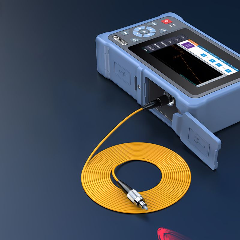
■ How to Perform OTDR Testing
OTDR (Optical Time Domain Reflectometer) will effectively serve as a device for the assurance of the quality of FTTH fiber deployment. The stringing reveals loss and bends due to splices, connectors, and breaks of fibers.
A. Recommended Testing Procedure
Prepare the following:
OTDR with dual wavelength (1310/1550nm or including 1625nm)
Launch fiber and receive fiber (reference cables)
Clean jumper and adapters
The OTDR Setup Suggestions:
Wavelength: 1310nm and 1550nm
Pulse width: 10-30 ns (short-range < 2 km)
Test range: 1.5-2 times the cable length.
Averaging time: 10-30 frames/s for sensor frame size of 50 MB would yield an average signal-to-noise ratio.
Enable the detection of events with consequent automated processing.
Testing Steps:
Remove contaminants, if any, from both of the ends of the cable.
Link the system using the following sequence: OTDR → Launch Fiber → Drop Cable (DUT) → Receive Fiber.
Begin the test, store the traces and the event table.
■ Key Parameters and Acceptance Criteria
The following parameters are essential for performance assessment:
Parameter | Definition | Typical Acceptance Criteria |
Insertion Loss (IL) | Total loss from input to output | ≤ 1.0 dB total or ≤ 0.4 dB/km |
Connector Loss | Loss at each connector point | ≤ 0.3 dB |
Splice Loss | Fusion splice point loss | ≤ 0.1 dB |
Return Loss | Back reflection of optical signal | ≥ -40 dB |
Event Uniformity | Absence of abnormal spikes or loss | No abrupt loss > 0.3 dB or strong reflections |
Note: Poor return loss (e.g., > -35 dB) may indicate dirty or loosely connected interfaces.
■ How to Detect Fiber Bending Issues
A. Macrobend Detection
Method: PCR filtering step with high wavelength (1550-1625nm).
Symptoms: Indentations that aren't uniform presenting at ripples along the trace; changes for 1310nm absent.
Common Causes: Poor flat walls and abrupt sharp angles in the internal wiring install.
B. Microbend Detection
Method: Use OTDR practical or power meter reflections to perceive gradual attenuation of the power in level of the trace.
Symptoms: Uncoatably inconsistent drop without definite event points reflecting.
Reasons: Excessive load through heavy connectors, clamp screw up, or endless tie mismatch.
Translation of OTDR high-wavelength measurements and illumination for a comprehensive result.
■ Recommended Testing Instruments
Brand | Model | Features | Application |
EXFO (Canada) | MaxTester 720C | Rugged design, rich reporting, dual wavelength | Telecom-grade FTTH deployment |
VIAVI (USA) | SmartOTDR 100B | Smart interface, automated analysis | Carrier-scale fiber rollout |
YOKOGAWA (Japan) | AQ1210 series | High accuracy, portable, cost-effective | Short-distance fiber links |
ShinewayTech (China) | PalmOTDR S20A | Compact, multi-wavelength | SME field testing |
Grandway (China) | FHO5000 | Affordable, complete functions | Entry-level field use |
ZC OTDR Series Product Comparison Table
Specification | |||||
PIC |  |  |  |
|  |
Screen Size | 5-inch touch screen | 7-inch capacitive touchscreen | 7-inch capacitive touchscreen | 7-inch capacitive touchscreen | 7-inch capacitive touchscreen |
Operating System | Embedded OS | Embedded OS | Embedded OS | Embedded OS | Linux OS, quad-core processor |
Max Dynamic Range | 32dB | 45dB | 42dB | 43dB | 45dB |
Event Dead Zone | 1.5m | 0.8m | 0.8m | 0.8m | 0.8m |
Attenuation Dead Zone | 8m | 4m | 4m | 4m | 4m |
Max Test Distance | 120km | 200km | 200km | 200km | 260–420km |
Storage Capacity | ≥8GB | ≥8GB | ≥8GB | ≥8GB | ≥12GB |
Wavelength Options | 1310/1550nm | Multiple options incl. 1625nm | 1310/1490/1550nm | 1310/1490/1550/1625nm | Multiple: incl. 1625nm & 1650nm |
VFL (Visual Fault Locator) | Yes | Yes | Yes | Yes | Yes, ≥10mW |
LS (Laser Source) | Yes | Yes | Yes | Yes | Yes, ≥-5dBm |
OPM (Optical Power Meter) | Yes | Yes | Yes | Yes | Yes |
End Face Detection | No | Supported | Supported | Supported | Supported |
PON Network Testing | Up to 1:8 splitter | Up to 1:64 splitter | Up to 1:64 splitter | Up to 1:64 splitter | Up to 1:64 splitter |
Report Export Format | PDF, SOR format | PDF, SOR format | PDF, SOR format | PDF, SOR format | PDF, SOR format (Chinese/English naming supported) |
USB Ports | 1×USB-A | 2×USB-A | 2×USB-A | 2×USB-A | 2×USB-A + Type-C |
Battery Capacity | 7.4V, 5000mAh | 7.4V, 5200mAh | 7.4V, 5200mAh | 7.4V, 5200mAh | 7.4V, 5200mAh |
Weight | <1kg | <1.2kg | <1.2kg | <1.2kg | <1.2kg |
Dimensions (mm) | 190×130×65 | 227×160×70 | 227×160×70 | 227×160×70 | 227×160×70 |
Other Functions | OTDR/VFL/OPM/LS | OTDR/VFL/OPM/LS/Event Map | Same, with 3-wavelength PON | Same, with higher performance | Same + Network Test, |

■ Next Step and Final Acceptance Advices
A. Suggested Acceptance Process:
Take the test plan and include acceptance limits in it.
Make sure that the cable routes and the cable arrangement.
Carry out combined OTDR and power meter examinations.
Signal repair actions for the links that show failing links.
Prepare an acceptance report with the saved test data.
B. Test Report Should Include:
The project name and the ID
The cable identification and the number of the fiber core
OTDR setting parameters (details on wavelength, range, and pulse)
Presentation of the event table and the screenshots of the trace
Writing down of the losses and reflections
Pass/fail expression
Signature and the date of the technician
■ Conclusion
Therefore, accurately testing FTTH Drop Cables and taking their acceptance guarantee not only project compliance but also the reliability of the ambience built and the satisfaction of the end-users. Companies are now confident in fibrous connections and bent fiber detection, hence the competent engagement of these professionals to produce high-quality connections focused on the FTTH technology.
For the editable acceptance report templates, such as English-Chinese OTDR result sheets or fibre testing equipment datasheets, you could contact our support team and request dedicated materials.

James is a technical manager and associate at Zion Communication.
Specializes in Optical Fiber communications, FTTH Solutions,
Fiber optic cables, ADSS cable, and ODN networks.
james@zion-communication.com
+86 13777460328
FTTH Drop Cable Installation: 30 Common Questions & Expert Answers
FTTH Drop Cable – Reliable Fiber-to-the-Home Solutions for Last-Mile Connectivity
FTTH Drop Cable Termination & Connection Guide | Low Loss Installation Tips
FTTH Drop Cable Testing and Acceptance Guide | OTDR Analysis, Loss Limits & Inspection Tips
FTTH Drop Cable Maintenance & Troubleshooting Guide | Easy Tips to Prevent Signal Loss
FTTH Drop Cable Installation Safety Guidelines | Avoid Mistakes Near Power Lines


