OPGW Cable Designs | Central & Stranded Stainless Steel Tube | Optical Ground Wire Solutions
Author: Site Editor Publish Time: 03-04-2025 Origin: Site
Optical Ground Wire (OPGW) combines an overhead shield wire with optical fibers. Installed at the top of a transmission line, its metallic elements carry lightning and fault current toward the grounding system, while the fibers support protection, control, monitoring, and telecommunications. The two main construction families are central-tube OPGW, with one optical unit at the cable center, and stranded-tube OPGW, with one or more stainless steel optical units incorporated into stranded metallic layers.
Neither family is universally better. Central-tube designs are often considered when compact diameter and lower mass are important; stranded-tube designs provide more freedom to balance fiber count, tensile strength, metallic area, and fault-current capacity. OPGW is not selected by voltage class alone. The final cable must match the line's spans, mechanical loads, short-circuit duty, lightning environment, fiber requirement, corrosion exposure, fittings, and installation method.
Central-Tube vs Stranded-Tube OPGW
The structural difference is the arrangement of the optical units and metallic layers. That arrangement affects the practical design range, but a construction name is not a performance rating. The supplier's final datasheet must be used for every comparison.
| Decision Point | Central-Tube OPGW | Stranded-Tube OPGW |
| Optical arrangement | One sealed optical unit at the center | One or more optical units within stranded layers |
| Typical reason to evaluate | Compact cable and controlled mass for a defined line envelope | Greater design flexibility for fibers, strength, and metallic capacity |
| Do not assume | That every design is suitable for direct ground-wire replacement | That every design has higher strength or fault-current capacity |
Why the metallic design still matters
The optical unit protects the fibers from moisture, strain, temperature cycling, and mechanical pressure. The surrounding wires provide tensile strength, electrical conductivity, and the external geometry needed for installation and long-term service. Aluminum-clad steel (ACS) wires are commonly used to combine strength, conductivity, and corrosion protection; aluminum alloy wires may be added when the design requires more conductive area or a different strength-to-weight balance.
Changing the number and size of optical units, wire materials, layer count, lay direction, or compaction changes cable diameter, mass, rated tensile strength, DC resistance, short-circuit capacity, and strain behavior. Common references include IEC 60794-4-10 and IEEE 1138, but the project specification must identify the required edition, test duty, and acceptance criteria.
Central Stainless Steel Tube OPGW
In a central stainless steel tube OPGW design, the fibers are housed in a sealed metal tube at the cable center. One or two layers of ACS wires, or a combination of ACS and aluminum alloy wires, are stranded around the optical unit. The compact arrangement can be useful when a replacement ground wire must stay within defined diameter, mass, sag, and tower-loading limits.
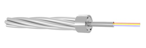
Suitability for an existing line still requires a line study. The designer should compare the proposed cable's final mass, diameter, rated tensile strength, elastic modulus, thermal expansion, creep and stress-strain data with the existing shield wire and the tower, hardware, clearance, and sag-tension limits.
Stranded Stainless Steel Tube OPGW
A stranded stainless steel tube OPGW design incorporates one or more stainless steel optical units into two or three stranded metallic layers. This arrangement can accommodate higher fiber counts and provides more design freedom for balancing tensile strength, metallic area, diameter, and short-circuit performance.

This construction is often considered for new lines or projects requiring additional fibers or higher mechanical capacity, but it is not automatically stronger or more suitable than every central-tube design. The final comparison must use the actual cable data and the project's loading cases.
Aluminum-Covered Stainless Steel Tube OPGW
An aluminum-covered stainless steel optical unit combines a sealed stainless steel tube with an external aluminum layer. The aluminum contributes conductive area and provides a compatible surface next to aluminum-bearing outer wires. Depending on the full metallic cross-section, this construction can help the designer meet project targets for electrical resistance, short-circuit energy, weight, and corrosion behavior.

Coastal or industrial exposure does not make one construction universally corrosion-proof. Material compatibility, pollution severity, salt exposure, drainage, hardware, and the specified corrosion tests all remain part of the engineering decision.
Aluminum Tube OPGW
An aluminum tube OPGW uses an aluminum optical unit surrounded by ACS wires or a mixture of ACS and aluminum alloy wires. The aluminum tube can add conductive area while sealing and mechanically protecting the optical core. A lighter or more conductive cable may be achievable for a particular design, but neither result should be assumed without comparing the completed cable specification.

The optical-unit sealing method, fiber strain margin, temperature behavior, electrical capacity, and resistance to crushing and vibration should be reviewed together. Material choice alone does not establish service life.
Compressed-Wire OPGW for Higher Lightning Duty
Some OPGW designs use shaped or compressed outer wires to increase metallic area within a controlled diameter and to modify the cable surface. This can support a design target for lightning or fault-current duty while also influencing mass, stiffness, tensile capacity, and fittings. It is more accurate to describe this as a project-engineered higher-duty option than as universally “lightning resistant.”

Required lightning test parameters, fault-current magnitude and duration, initial and final temperatures, grounding conditions, and acceptance criteria should be stated in the procurement specification. The matching suspension, dead-end, damper, splice, and grounding hardware must also be confirmed for the exact cable.
OPPC Is a Different Conductor Application
Optical Phase Conductor (OPPC) integrates optical fibers into an energized phase conductor. Unlike OPGW, it is not the overhead ground wire and does not replace the shield wire's line-protection function. OPPC may be considered where a line has no shield wire or where optical capacity is required in the phase position, but its insulation coordination, joints, fittings, installation procedures, and live-conductor safety requirements differ substantially from those of OPGW.

For that reason, OPPC should be evaluated as a separate conductor system rather than included in an OPGW comparison as though the two products perform the same electrical role.
OPGW Design Comparison
| Construction | Typical Design Purpose | Key Checks |
| Central stainless steel tube | Compact optical core; useful where diameter and mass are tightly controlled | Fiber count, strain margin, metallic area, sag-tension compatibility |
| Stranded stainless steel tubes | Multiple optical units; flexible balance of fiber and metallic capacity | Tube count, cable diameter, strength, short-circuit duty, hardware |
| Aluminum-covered stainless steel tube | Sealed steel tube with added conductive aluminum layer | Electrical resistance, thermal duty, material compatibility, corrosion tests |
| Aluminum tube | Conductive optical unit with integrated sealing and protection | Sealing, crush resistance, strain margin, vibration and temperature behavior |
| Compressed outer wires | More metallic area or a selected surface profile within design limits | Lightning test duty, fault current, stiffness, fittings, installation tension |
Information Needed to Specify OPGW
Line and route: nominal voltage, tower configuration, span lengths, ruling span, elevations, crossings, wind, ice, temperature range, pollution, and corrosion exposure.
Mechanical requirements: required tensile strength, maximum installation and everyday tension, diameter and mass limits, sag-tension data, creep, elastic modulus, thermal expansion, and vibration conditions.
Electrical requirements: fault-current magnitude and duration, initial and final temperatures, DC resistance, required lightning duty, and grounding arrangement.
Optical requirements: fiber count and type, attenuation limits, fiber strain limits, proof-test level, identification, splice plan, and acceptance measurements.
Installation and hardware: drum length, pulling method, sheave requirements, minimum bending diameter, suspension and dead-end sets, dampers, joints, downleads, grounding clamps, and splice closures.
Quality documentation: applicable standard editions, type tests, routine tests, sample tests, inspection plan, traceability, packing, and delivery records.
ZION's current OPGW cable range includes central-tube, stranded-tube, aluminum-covered, aluminum-tube, and compressed-wire options. The final cable and hardware set should be selected from verified project inputs, not from a generic voltage label.
OPGW Cable Production
Manufacturing controls should protect the optical unit, maintain the specified strand geometry, and keep the finished cable within the approved mechanical, electrical, and optical tolerances. The production plan should also preserve material traceability and define routine testing for the delivered drum lengths.
Frequently Asked Questions
What is the main difference between central-tube and stranded-tube OPGW?
Central-tube OPGW places the optical fibers in one central metal tube. Stranded-tube OPGW uses multiple optical units stranded with metallic elements. The second arrangement can offer more design flexibility for fiber count and metallic capacity, while the best option depends on the complete project specification.
Can OPGW be selected only by transmission-line voltage?
No. Voltage class provides context but does not define the required OPGW. Mechanical loading, spans, fault current, lightning exposure, grounding, fiber count, environment, fittings, and installation constraints determine the cable design.
Is compressed-wire OPGW immune to lightning damage?
No OPGW construction should be described as immune to lightning damage. Compressed or shaped wires may help achieve a specified metallic area and lightning-duty target, but performance must be demonstrated against the project's test parameters and acceptance criteria.
Is OPPC another type of OPGW?
No. OPGW is an overhead ground or shield wire with optical fibers. OPPC is an energized phase conductor with optical fibers. They occupy different positions and require different system, safety, insulation, hardware, and installation engineering.



 Fiber Optic Tools
Products 6 families
Solutions 6 markets
Resources Tools & docs
Certificate
Certification and compliance references for project review, qualification and purchasing documentation.

 Fiber Optic CableAccess and backbone
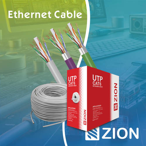 Ethernet CableCat5e to Cat8
 Coaxial CableRF and video signal
 Fire, Security & AlarmSafety systems
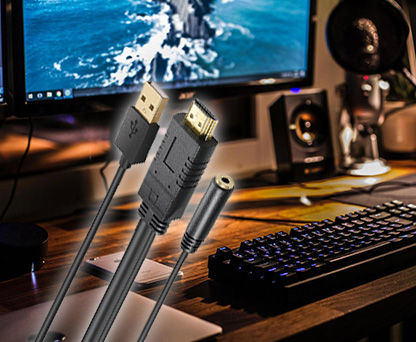 Voice, Audio & VideoSignal cabling
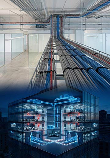 Power & Control CableEnergy and control
Fiber optic cable systems
Outdoor, indoor, FTTH and distribution cable lines for access networks, backbone routes and campus deployments.
 Telecom & ISP NetworksFTTH, PON, ODN
 Data Center InfrastructureServer room cabling
 Building Low-Voltage SystemsBMS, AV, weak current
 Security & Fire ProtectionAlarm, CCTV, access
 Industrial Automation CablePLC, RS485, fieldbus
 Energy & Power InfrastructureSolar, battery, power
Telecom & ISP Networks
For FTTH / PON access, outdoor fiber deployment, aerial routes, duct routes, direct burial routes, rural broadband and ODN planning.
Tools
Use calculators and planning tools for conduit capacity, PoE voltage drop and fiber optic link loss budget work.