- Fiber Optic Cables
- ADSS cable
- ADSS Single jacket
- ADSS 80M Single Sheath
No classification
- ADSS 100M Single Sheath
No classification
- ADSS 120M Single Sheath
No classification
- ADSS 80M Single Sheath
- ADSS Double sheath
No classification
- ADSS Single jacket
- FTTH Drop Cable
No classification
- FTTH Drop Patch Cord
No classification
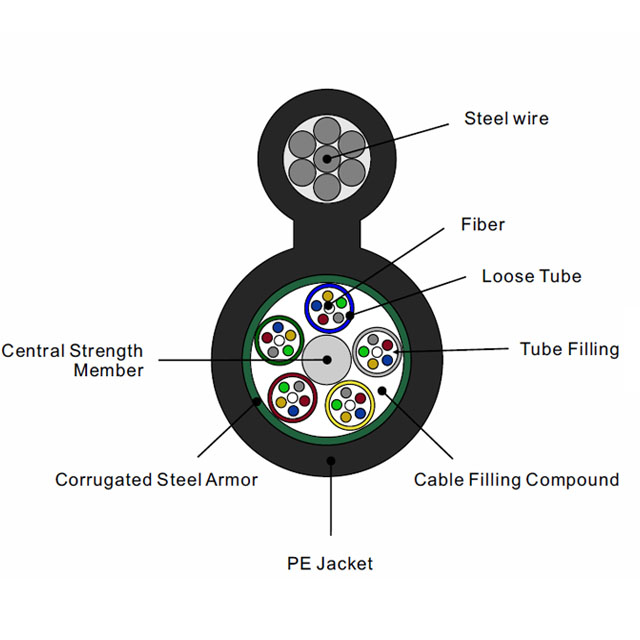
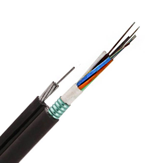
- Aerial Fiber Optic Cable
No classification
- OPGW
No classification
- Duct Fiber Optic Cable
No classification
- Direct Buried Fiber Optic Cable
No classification
- Air Blown Micro Cable
No classification
- Building Cabling Fiber
No classification
- Rural Network Fiber Optic Cable
No classification
- Space-Saving Fiber Optic Cable
No classification
- Distributed Base Station Fiber Optic Cable
No classification
- Rodent Resistant Fiber Optic Cable
No classification
- Fire-Resistant Fiber Cable
No classification
- Fiber Optic Tether System
- FPV Drone
No classification
- FPV Fiber Optic Spool
No classification
- Fiber Optic Guidance Wire
No classification
- FPV Drone
- ADSS cable
- Fiber Optic Tools
- Fiber Optic Installation Tools/Accessories/Fittings
- ADSS Cable Guy Grips
No classification
- ADSS Cable Suspension Grips
No classification
- OPGW Cable Guy Grips
No classification
- OPGW Cable Suspension Grips
No classification
- Stainless steel strip &buckle
No classification
- Stainless Banding Tool
No classification
- Aluminum hoop&Pole Bracket
No classification
- Hoop Retractor&Pole Brackets
No classification
- Fittings
No classification
- Immobility Clamp
No classification
- ADSS Cable Guy Grips
- FTTH Fiber Optic Tools
- FTTH stainless steel flat drop cable clamp
No classification
- FTTH nylon cable flat drop cable clamp
No classification
- FTTH combination flat drop cable clamp
No classification
- FTTH Hook
No classification
- FTTX ADSS Suspension clamp
No classification
- FTTX ADSS Tension clamp
No classification
- FTTH stainless steel flat drop cable clamp
- Fiber Termination Tools
No classification
- Fiber Optic Test Tools
No classification
- OTDR Accessories
No classification
- Fiber Optic Cleaning Tools
No classification
- Fiber Optic Installation Tools/Accessories/Fittings
- LAN/Ethernet Cable
- CAT8
No classification
- CAT7 / CAT7A
- CAT7
No classification
- CAT7A
No classification
- CAT7
- CAT6A
- U/UTP
No classification
- U/FTP
No classification
- F/UTP
No classification
- F/FTP
No classification
- S/FTP
No classification
- CAT6A AMOUR/CST
No classification
- U/UTP
- CAT6
- U/UTP
No classification
- F/UTP
No classification
- SF/UTP
No classification
- Dual
No classification
- Armour CAT6
No classification
- U/UTP
- CAT5E
- U/UTP
No classification
- F/UTP
No classification
- SF/UTP
No classification
- Dual
No classification
- U/UTP
- Copper Patch Cord Cable
- CAT5E
No classification
- CAT6
No classification
- CAT6A
No classification
- CAT7
No classification
- CAT7A
No classification
- CAT8
No classification
- Special type
No classification
- CAT5E
- Ethernet Plenum Cable
No classification
- Network Cable
No classification
- Copper Trunk Cable
No classification
- Direct-Burial Outdoor Ethernet Cables
No classification
- CAT8
- Coaxial Cable
- Low Loss Cable
No classification
- RF Corrugated Coax Cable
- 1/4"
No classification
- 3/8"
No classification
- 1/2"
No classification
- 7/8"
No classification
- 1 1/4"
No classification
- 1 5/8"
No classification
- 1/4"
- Radiating Leaky Coaxial Cable
No classification
- RG MIL-C-17 Cable
No classification
- PTFE-FEP Coaxial Cable
No classification
- D-FB Coax Cable
- D-FB cable
No classification
- Connectors for D-FB cable
No classification
- Grounding Kit, Clamp, Weatherproof for D-FB cable
No classification
- D-FB cable
- 75 ohm Coaxial Cable
- RG6 coax cable
- RG6 S
No classification
- RG6 Tri
No classification
- RG6 Q
No classification
- RG6 Dual
No classification
- RG6 S
- RG59 coax cable
- RG59 S
No classification
- RG59 Tri
No classification
- RG59 Q
No classification
- RG59 S
- RG11
- RG11 S
No classification
- RG11 Tri
No classification
- RG11 Q
No classification
- RG11 S
- SAT coax cable
No classification
- HD coaxial cable
No classification
- VHF Leaky Feeder Cable
No classification
- Trunk cable/Hardline cable
- PS
No classification
- QR
No classification
- PS
- CT coax cable
No classification
- KX coax cable
No classification
- VATC coax cable
No classification
- PK75 coax cable
No classification
- RG6 coax cable
- Plenum Coaxial Cable
No classification
- EN 50117 Coaxial Cable
- Broadband double shield SA Class A++ >105dB
No classification
- Broadband Triple shield SA Class A++ >105dB
No classification
- Digital Drop shield SA Class A+>95dB
No classification
- Digital Drop shield SA Class A>85dB
No classification
- Broadband double shield SA Class A++ >105dB
- Coaxial Jumper Cables
- 1/2" Super Flex Jumper Cable
No classification
- 1/2" Feeder Jumper Cable
No classification
- 3/8" Super Flex Jumper Cable
No classification
- 1/4" Super Flex Jumper Cable
No classification
- RG141 Jumper Cable
No classification
- RG142 Jumer Cable
No classification
- RG58 Jumper Cable
No classification
- 1/2" Super Flex Jumper Cable
- 50 Ohm Coaxial Cable
No classification
- Semi-Flexible Series Cable
No classification
- Low Loss Cable
- Fire, Security & Alarm Cable
- Fire Cables
No classification
- Fire Resistance Cable
- EN50200 PH30 Cable
No classification
- EN50200 PH120 Cable
No classification
- JB-Fire Alarm Cable
No classification
- Standard BS 6387 Cable
No classification
- Standard BS 7629 Cable
No classification
- FRLS & FRFH
- FRLS & FRFH Unshielded
No classification
- FRLS & FRFH Shielded
No classification
- FRLS & FRFH Unshielded
- Silicon Insulation
No classification
- EN50200 PH30 Cable
- Fire Alarm Cable
- UL Fire alarm cable-MENA
No classification
- UL 1424 FPL Unshielded
No classification
- UL 1424 FPLR Unshielded
No classification
- UL 1424 FPLP Unshielded
No classification
- UL 1424 FPL Shielded
No classification
- UL 1424 FPLR Shielded
No classification
- UL 1424 FPLP Shielded
No classification
- UL 1424 Solid
- UL 1424 Solid S
No classification
- UL 1424 Solid U
No classification
- UL 1424 Solid S
- UL 1424 Stranded
- UL 1424 Stranded U
No classification
- UL 1424 Stranded S
No classification
- UL 1424 Stranded U
- UL Standard
No classification
- UL Fire alarm cable-MENA
- CCTV Surveillance Cable
- Siamese Coaxial Cable
- RG59+2c
No classification
- RG6+2c
No classification
- Other
No classification
- RG59+2c
- Siamese Ethernet Cable
No classification
- KVK CCTV Cable
- КВК-В-1,5
No classification
- КВК-В-2Э
No classification
- КВК-П-1,5
No classification
- КВК-П-2Э
No classification
- КВК-В-1,5
- Custom CCTV Combined Cable
- HD
No classification
- PTZ
No classification
- RG59
No classification
- MENA
No classification
- HD
- RG6 CCTV
No classification
- RG59 CCTV
No classification
- RG11 CCTV
No classification
- PK75 CCTV
- Паракс РК 75-2-110
No classification
- Паракс РК 75-2-111
No classification
- Паракс РК 75-2-122
No classification
- Паракс РК 75-2-13M
No classification
- Паракс РК 75-2-310
No classification
- Паракс РК 75-2-311
No classification
- Паракс РК 75-3-313 нг(А)
No classification
- Паракс РК 75-3-314 нг(А)
No classification
- Паракс РК 75-3-315 нг(А)
No classification
- Паракс РК 75-3-316 нг(А)
No classification
- Паракс РК 75-3-32
No classification
- Паракс РК 75-3-322
No classification
- Паракс РК 75-2-110
- JIS C CCTV
No classification
- MINI CCTV
No classification
- Other
No classification
- Siamese Coaxial Cable
- Burglar Alarm cable
- Alarm, signal cable
No classification
- Mylar Pair Cable
No classification
- Solid Cond. global alarm cable
No classification
- Stranded Cond.unshielded global alarm cable
No classification
- Stranded Cond.shielded global alarm cable
No classification
- UL Standard security,sound, alarm cable
No classification
- General Purpose
No classification
- Alarm, signal cable
- Access Control Cable
No classification
- Fire Alarm System
- Cables De Alarma Incendio
No classification
- Cabos De Alarme De IncÊndio
No classification
- Cables De Alarma Incendio
- Lutron Cables
No classification
- Plenum Security Cables
No classification
- Fire Cables
- Voice, Audio & Video Cable
- Flat Telephone Cable
No classification
- Circular Audio Speaker Cable
No classification
- Circular Shielded Audio Cable
No classification
- Multicore Circular Speaker Cable
No classification
- Parallel Speaker Cable
No classification
- Media Composite Cable
No classification
- Coax Jumper Cable/F Type Cable
No classification
- Audio Speaker Cable
No classification
- Audio XLR Cable
No classification
- HDMI
- HDMI Cable
No classification
- HDMI Extender
No classification
- HDMI Cable
- DisplayPort Cable
No classification
- DVI Cable
No classification
- VGA Cable
No classification
- Adaptors
No classification
- Flat Telephone Cable
- Universal Serial Bus
- USB C Cable
No classification
- USB C Converter
No classification
- USB Cable
No classification
- USB Hub
No classification
- USB to Serial Cable
No classification
- USB Bluetooth/Network/Sound Adapter
No classification
- USB C Cable
- Control Cable
- Fieldbus Cable
No classification
- Industrial Ethernet Cable
No classification
- PROFINET Cable
No classification
- Marine LAN Cable
No classification
- Flexible Control Cable
No classification
- Chain Cable
No classification
- SERVO Motor Cables
No classification
- Robotics Cables
No classification
- Fieldbus Cable
- Power & Control Cable
- Solar Cable
- H1Z2Z2-1 Single
No classification
- H1Z2Z2-1 Twin
No classification
- UL4703
No classification
- TUV 2 pfG 2642/01.22
No classification
- Material
No classification
- H1Z2Z2-1 Single
- Battery Cable
No classification
- General Power Cable
No classification
- KNX Cable
No classification
- LV Armoured Cable SWA & AWA
No classification
- Automotive cable
- American Standard
- American Standard Battery Wire
No classification
- American Standard Primary Wire
No classification
- American Standard-More Type Wire
No classification
- American Standard Battery Wire
- Germany Standard
No classification
- Japanese Standard
No classification
- American Standard
- High Temperature Cable
- Silicone 180℃ cable
No classification
- Silicone 200℃ cable
No classification
- Silicone 450℃ cable
No classification
- Silicone 180℃ cable
- Flex Control Cable
No classification
- Sensor & Actuator Cables
No classification
- Hook Up wire
No classification
- Solar Cable
- other
- Cable Materials
- CCA WIRE
No classification
- CCAM WIRE
No classification
- Aluminum Foil
No classification
- Al-Mg alloy wire
No classification
- CCS WIRE
No classification
- Enameled aluminum wire(EAL)
No classification
- Enameled copper clad aluminum wire (ECCA)
No classification
- Enameled copper wire(EC)
No classification
- TCCA WIRE
No classification
- TCCAM WIRE
No classification
- Galvanized Steel Wire
No classification
- Stranded Wire
No classification
- CCA WIRE
- Cable Materials
Please select superior classification
Please select superior classification
Please select superior classification
Please select superior classification