News Details
How to Test MPO Fiber Links: Insertion Loss, Polarity & Acceptance Guide
Author: James Publish Time: 30-03-2026 Origin: Site
How to Test MPO Fiber Links
A practical engineering reference for verifying MPO link loss, polarity, acceptance readiness, and troubleshooting logic before turn-up or project handover.
Do not start with power measurement alone. Inspect and clean MPO end faces first.
Insertion loss and polarity are the two most important pass/fail checks for installed MPO links.
When a link is marginal, move from simple pass/fail testing to lane-level fault isolation.
■ 1) What This Test Covers
Testing an MPO fiber link is not only about checking whether light passes through the channel. The real goal is to confirm that the link can be accepted, documented, and trusted in production service. For engineers and project teams, that means verifying lane integrity, loss consistency, polarity correctness, and overall readiness for the target application.
In practical deployment, MPO links introduce higher density and tighter tolerance than simple duplex fiber. A single connector can affect multiple lanes at once, so one contaminated interface or one polarity mismatch can create multiple failures. That is why MPO testing should follow a structured workflow rather than an ad hoc field check.
| Test item | What it confirms | Why it matters |
|---|---|---|
| Insertion loss | Channel attenuation by lane | Determines whether the link fits the application budget |
| Polarity | Correct Tx/Rx lane mapping | A low-loss link can still fail if mapping is wrong |
| Length / continuity | Basic channel structure and routing consistency | Helps validate build intent and isolate unexpected path issues |
| Return loss / reflectance | Reflection behavior at events and interfaces | Important for stricter single-mode or troubleshooting cases |
■ 2) Testing Purpose
The first purpose of MPO testing is installation acceptance. Before a data center row, backbone zone, or cross-connect panel is handed over, the team needs objective evidence that the channel behaves as designed. That means confirming the link is not only continuous, but also aligned with the expected loss and mapping logic.
The second purpose is risk control. High-density fiber channels often sit inside larger projects with strict schedules. If testing is delayed until activation, the team may discover polarity errors, dirty connectors, or lane imbalance only after switch ports are already assigned. That increases rework cost and slows commissioning.
| Project stage | Primary test goal | Typical output |
|---|---|---|
| Pre-installation check | Validate components and cleanliness | Visual inspection record |
| Post-installation certification | Verify loss, continuity, polarity | Acceptance test report |
| Commissioning support | Confirm link readiness for service | Go-live validation notes |
| Fault isolation | Locate high-loss or wrong-mapped lanes | Corrective action list |
■ 3) Insertion Loss Testing
Insertion loss testing is the core acceptance step for most MPO links. It measures how much optical signal is lost from one end of the channel to the other. For engineering teams, this is the fastest way to determine whether the installed channel still fits the expected operating margin.
A useful field rule is simple: do not evaluate insertion loss without first controlling the test setup. Clean interfaces, correct reference method, correct wavelength selection, and appropriate test cords all affect the final result. A poor test method can produce a false fail or a misleading pass.
Recommended workflow
Inspect MPO end faces before mating.
Clean if necessary and re-inspect.
Set the reference using the intended test method.
Measure each lane across the complete channel.
Compare results against the project loss budget, not a casual field guess.
| Checkpoint | Why it matters | Typical risk if ignored |
|---|---|---|
| Connector inspection | Prevents contamination from affecting multiple fibers | Artificially high lane loss |
| Reference method | Defines the baseline for measurement | Inconsistent pass/fail result |
| Lane-by-lane reading | Reveals imbalance hidden by average numbers | Undetected weak lane |
| Budget comparison | Connects measurement to real application margin | Passing the test but failing the service later |
■ 4) Polarity Verification
A link can show acceptable insertion loss and still be unusable if polarity is wrong. MPO systems depend on correct lane mapping between transmit and receive positions. That mapping must stay consistent across trunks, cassettes, patch cords, and equipment ports.
In field work, polarity problems usually come from mixed design assumptions rather than a single damaged component. For example, a team may install a trunk based on one polarity logic and then patch it with a cassette or harness designed for another. The result is a clean but nonworking channel.
| Scenario | What to verify | Common failure mode |
|---|---|---|
| Backbone trunk only | Lane continuity and expected position mapping | Reversed array relationship |
| Trunk + cassette path | End-to-end Tx/Rx routing logic | Cassette method mismatch |
| Trunk + harness path | Equipment port breakout sequence | Wrong fan-out sequence or branch assignment |
| Patch replacement | Pinned / unpinned and mapping consistency | Physical mate mismatch or logical reversal |
■ 5) Return Loss and Acceptance
For many installed MPO links, the first pass/fail layer focuses on insertion loss, continuity, and polarity. However, some projects require deeper acceptance logic. If the application has tighter optical margin or the channel includes sensitive interfaces, return loss and reflectance become more important.
From an engineering standpoint, acceptance should not rely on one number alone. A link should be considered acceptable only when the lane loss pattern is stable, the mapping is correct, and the result aligns with the project budget and expected use case. When these conditions do not align, deeper fault localization is justified.
| Acceptance layer | Primary question | When to use |
|---|---|---|
| Basic link certification | Does the installed channel meet expected loss and continuity? | Routine project acceptance |
| Polarity validation | Do lanes arrive at the intended positions? | All MPO systems |
| Reflectance review | Are reflection-related events affecting the link? | Stricter channels or unstable results |
| Fault localization | Where exactly is the problematic event or lane? | Failure analysis and rework planning |
■ 6) Common Mistakes and Risks
Most MPO test failures come from process mistakes rather than catastrophic cable defects. Because MPO connectors carry multiple fibers in one interface, a small error can have a disproportionate effect. This is especially true when teams are working under schedule pressure and skip inspection or documentation.
The most frequent field problems are dirty interfaces, poor reference control, wrong polarity assumptions, and untracked patch changes. These issues raise rework cost because they often appear after rack installation is complete, when the physical path is already crowded and harder to reopen.
| Mistake | Immediate effect | Project impact |
|---|---|---|
| Skipping connector inspection | Unexpected loss on several lanes | Repeated retesting and contamination spread |
| Using the wrong reference setup | Inconsistent readings | False fail or false pass |
| Mixing polarity methods | Link does not operate even with acceptable loss | Commissioning delay |
| Replacing patching without records | Loss of traceability | Longer troubleshooting time and higher maintenance cost |
■ 7) Decision Rules / Engineer’s Shortcut
The fastest way to manage MPO testing is to match the problem type to the correct response. Not every failure needs a full escalation, but not every pass is safe to approve either. The table below provides a practical decision shortcut for engineering and project teams.
| Observed result | Most likely issue | Fastest next action | Decision |
|---|---|---|---|
| All lanes pass and mapping is correct | No active issue detected | Archive test report and hand over | Accept |
| Several adjacent lanes show high loss | Contamination or interface issue | Inspect, clean, retest | Hold acceptance |
| Loss is acceptable but the link does not work | Polarity or mapping mismatch | Verify end-to-end lane mapping | Reject until corrected |
| One or two lanes fail repeatedly | Localized connector or branch issue | Swap interface path or isolate lane | Targeted rework |
| Results change between repeated tests | Unstable setup, poor referencing, or handling issue | Rebuild test setup and control handling | Do not accept yet |
■ 8) Application Scenarios
MPO link testing is relevant across multiple deployment models, but the testing emphasis changes by environment. A structured cabling contractor may focus on acceptance efficiency and documentation quality, while a data center operations team may care more about upgrade readiness and future troubleshooting speed.
| Application scenario | Primary concern | Recommended emphasis |
|---|---|---|
| New data center backbone | Acceptance and future scalability | Loss, polarity, and full documentation |
| MDA to EDA distribution | Service turn-up reliability | Lane mapping and clean patching records |
| Migration or upgrade project | Compatibility and margin review | Compare existing link condition against new budget |
| Fault remediation | Fast isolation with minimal rework | Pattern recognition and event localization |
■ 9) FAQ
Is insertion loss testing enough for an MPO link?
Not by itself. Insertion loss confirms attenuation performance, but MPO acceptance also depends on correct polarity and lane mapping. A low-loss link can still fail in service if the Tx/Rx relationship is wrong.
When should return loss or deeper troubleshooting be added?
Add deeper analysis when results are marginal, unstable between repeated tests, or tied to a stricter application requirement. It is also useful when the link appears to pass basic certification but still behaves poorly in operation.
What is the most common field mistake during MPO testing?
Skipping end-face inspection is the most common and most avoidable mistake. In MPO systems, contamination can affect multiple fibers at once and create misleading results that look like trunk defects.
Can different MPO components be mixed if the connector type is the same?
Physical compatibility does not guarantee logical compatibility. Trunks, cassettes, harnesses, and patch cords must follow the same polarity and mapping plan, otherwise the channel may test partially correct but fail in service.
What should procurement or project teams ask suppliers before approval?
Ask for the test method, polarity method, connector type, lane configuration, and target application assumptions. These points help prevent acceptance disputes and reduce the risk of ordering components that are mechanically similar but operationally mismatched.
Can customized MPO assemblies be tested before shipment?
Yes. For customized assemblies, pre-shipment testing and clear reporting are strongly recommended. This is especially important when fiber count, polarity logic, connector gender, branch mapping, or loss targets differ from standard stock configurations.
■ 10) Conclusion
Testing MPO fiber links is an engineering control process, not a formality. The most reliable workflow is to inspect first, verify insertion loss lane by lane, confirm polarity, and then escalate to deeper analysis only when the failure pattern or application requirement justifies it. This approach reduces acceptance disputes, avoids unnecessary rework, and gives operations teams a better baseline for future maintenance.
For project execution, the most actionable recommendation is to lock three things before deployment: the polarity plan, the test method, and the reporting format. Once these are defined early, MPO acceptance becomes faster, cleaner, and easier to scale across multiple links.
Need help confirming fiber count, polarity method, connector gender, loss target, branch mapping, or customized MPO assembly requirements? Send your project parameters and ZION can help review the configuration before sampling or quotation.
-
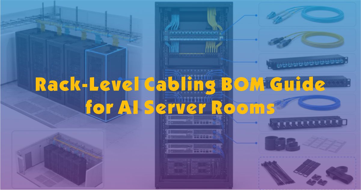 [Copper Communication] Rack-Level Cabling BOM Guide for AI Server RoomsLearn how to build a rack-level cabling BOM for AI server rooms, covering fiber uplinks, copper management links, patch cords, patch panels, cable managers, labels, spare ports and rack-based packing. Read More
 -
 [Security&Fire Protection] Security Cable RFQ Checklist for LATAM ProjectsPrepare a complete security cable RFQ for LATAM projects before ESS+ Colombia 2026, covering CCTV, access control, alarm, fire cable, shielding, jacket, certificates, packing and delivery terms. Read More
 -
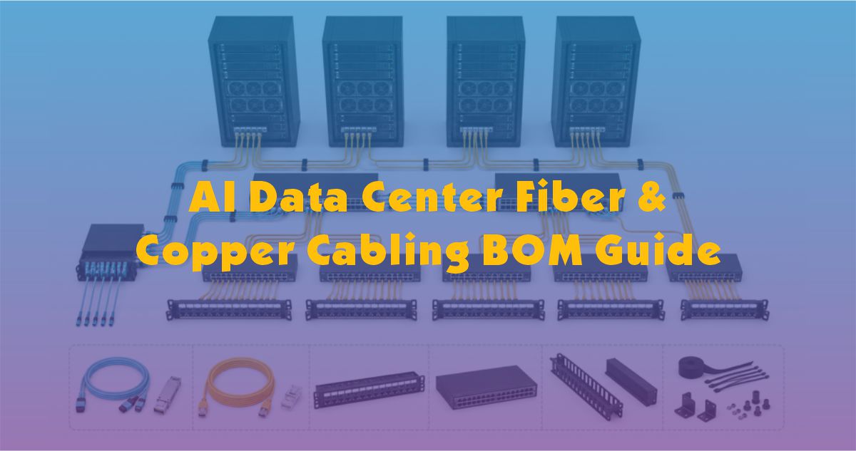 [Copper Communication] AI Data Center Fiber & Copper Cabling BOM GuideLearn why AI data centers need structured fiber and copper cabling BOMs to plan backbone links, management networks, rack cabling, patch panels, labeling, spare capacity and future upgrades. Read More


