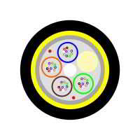
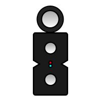
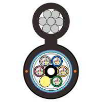
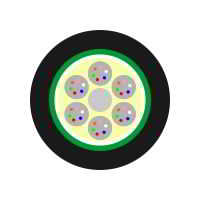
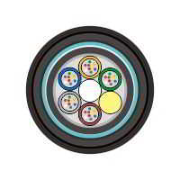
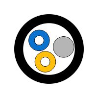
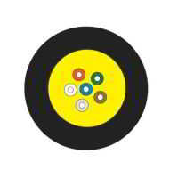
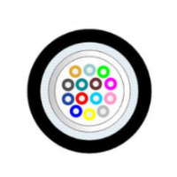
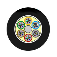
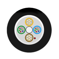
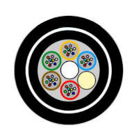
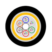
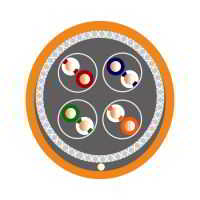
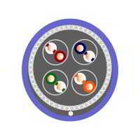
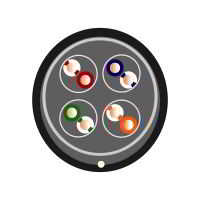
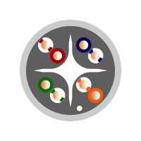
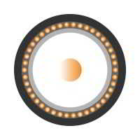
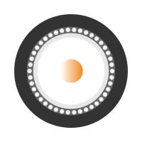
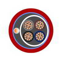
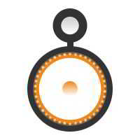
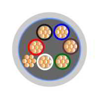
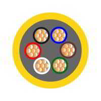
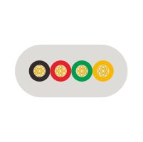
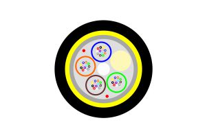
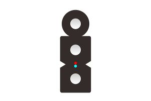
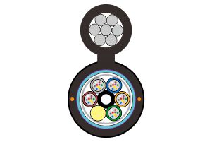
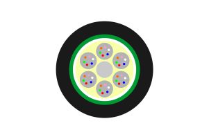
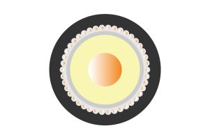
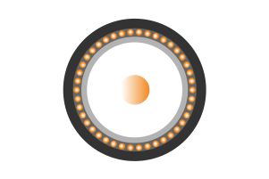
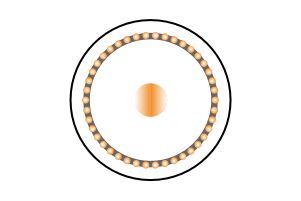
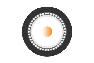
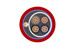
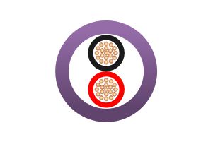
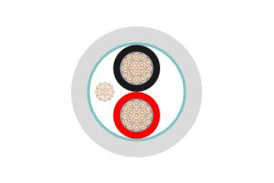
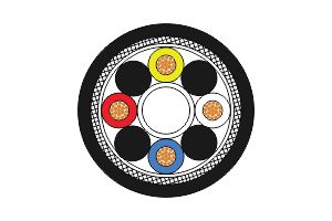
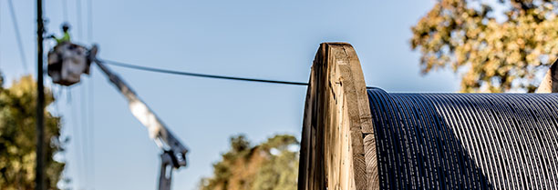
Dieléctricos y autosoportados (ADSS)
N/M
N/M
Cables de fibra óptica
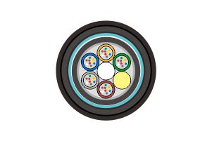
De 6 a 60 fibras (5tubos+1Central)
ISO9001
3km/carrete
Carrete de madera,Φ1100*750mm
40 km
5-25 Dias
NINGBO CHINA
30% TT como depósito, 70% restante antes del envío.
Availability: | |
---|---|
Dieléctricos y autosoportados | |||||||||||
Introduction | |||||||||||
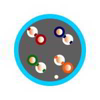
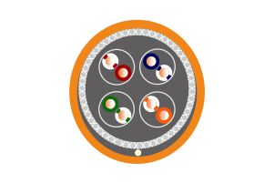
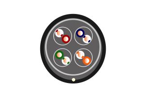
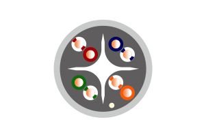
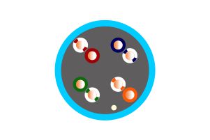
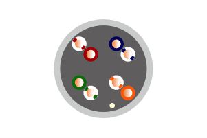
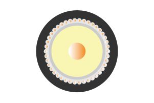
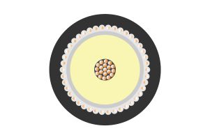
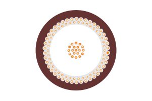
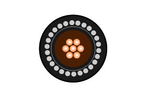
ADSS cable is loose tube stranded. Fiber, 250μm, are positioned in a loose tube made of a high modulus plastic. The tubes are filled with a water-resistant filling compound. The tubes(and fillers) are stranded around a FRP(Fiber Reinforced Plastic ) as a non-metallic central strength member into a compact and circular cable core. After the cable core is filled with filling compound, it is covered with thin PE(polyethylene) inner sheath. After stranded layer of aramid yarns are applied over the inner sheath as strength member, the cable is completed with PE or AT(anti-tracking) outer sheath. | |||||||||||
| |||||||||||
Features and Applications | |||||||||||
√ High tensile strength | |||||||||||
√ All dielectric structure and semi-dry core design | |||||||||||
√ Small diameter and light weight | |||||||||||
√ Self-supporting aerial installation | |||||||||||
Technical data | |||||||||||
Numbers of fibers | 4-12F;14-36F;36-48F | ||||||||||
Fiber type | Single mode G.652.D/ Monomode | ||||||||||
Strength Member | Aramid Yard | ||||||||||
Loose Tube | 2.1mm-3.0mm PBT | ||||||||||
Filler Rope | FRP | ||||||||||
Water Blocking Layer(Material) | Waterproof GEL-filled/Water Blocking Compound | ||||||||||
Additional Strength Member(Material) | Aramid yarn | ||||||||||
Outer Sheath | PE/AT jacket | ||||||||||
Cable Diameter(±0.2mm) | 8.0mm-12.5mm | ||||||||||
Cable Weight(±10.0kg/km) | 85-150kg | ||||||||||
Attenuation coefficient | @ 1310nm≤0.35dB; @ 1550nm ≤0.2dB | ||||||||||
Min. bending radius Without Tension | 10.0×Cable-φ | ||||||||||
Min. bending radius Under Maximum Tension | 20.0×Cable-φ | ||||||||||
Standards | |||||||||||
■ ITU-T Rec. G.657A | ■ ISO9001 | ||||||||||
■ IEC 60794 | ■ ICEA-596 | ||||||||||
■ GR-409 | ■ YD/T 1997-2009 | ||||||||||
Colors -12 Chromatography | |||||||||||
No. | 1 | 2 | 3 | 4 | 5 | 6 | |||||
Color | Roja | Azul | Verde | Amarilla | Violeta | Blanca | |||||
No. | 7 | 8 | 9 | 10 | 11 | 12 | |||||
Color | Naranja | Gris | Marrón | Negro | Agua | Rosada | |||||
Fiber Optical Test Datas | |||||||||||
The properties of single mode optical fiber (ITU-T Rec. G652|G657) | |||||||||||
Transmission Characteristics | |||||||||||
850nm (multimode optical fiber communication system) | G.652.D | G.652.D | G.657.A1 | G.657.A2 | Unit | ||||||
@1310 nm | ≤0.35 | ≤0.34 | ≤0.34 | ≤0.34 | dB/km | ||||||
@1285-1330 nm | ≤0.37 | ≤0.37 | ≤0.37 | dB/km | |||||||
@1383 nm | ≤0.30 | ≤0.30 | ≤0.31 | ≤0.31 | dB/km | ||||||
@1460 nm | |||||||||||
@1490 nm | ≤0.24 | ≤0.23 | ≤0.23 | dB/km | |||||||
@1550 nm | ≤0.22 | ≤0.21 | ≤0.2 | ≤0.2 | dB/km | ||||||
@1525-1575 nm | ≤0.22 | ≤0.21 | ≤0.21 | dB/km | |||||||
@1625 nm | ≤0.25 | ≤0.24 | ≤0.22 | ≤0.22 | dB/km | ||||||
Mode Field Diameter | @1310 nm | 8.6±0.4 | 9.0±0.4 | 9.0±0.3 | 8.6±0.4 | µm | |||||
@1550 nm | 9.8±0.5 | 10.2±0.4 | 10.2±0.4 | 9.6±0.5 | µm | ||||||
Cable Cut-off wavelength(λ cc) | ≤1260 | ≤1260 | ≤1260 | ≤1260 | nm | ||||||
Zero Dispersion Wavelength | 1300-1324 | 1300-1324 | 1300-1324 | 1300-1324 | nm | ||||||
Zero Dispersion Slope | ≤0.092 | ≤0.092 | ≤0.09 | ≤0.09 | ps/nm²/km | ||||||
Dispersion Coefficient | @1285-1339 nm | ≤3.4 | ≤3 | ≤3.4 | ps/(nm·km) | ||||||
@1271-1360 nm | ≤5.3 | ps/(nm·km) | |||||||||
1525-1575nm | |||||||||||
1530-1565nm | |||||||||||
1565-1625nm | |||||||||||
@1550 nm | ≤ 18 | ≤ 18 | ≤ 17 | ≤ 18 | ps/(nm·km) | ||||||
@1625 nm | ≤ 22 | ≤ 22 | ≤ 21 | ≤ 22 | ps/(nm·km) | ||||||
PMD Maximum Individual Fiber | ≤0.1 | ≤0.1 | ≤0.1 | ≤0.1 | ps√km | ||||||
PMD Link Design Value | ≤0.06 | ≤0.06 | ≤0.06 | ≤0.06 | ps/√km | ||||||
Point Discontinuity | @1310 nm | ≤0.05 | ≤0.05 | ≤0.05 | ≤0.05 | dB | |||||
EGRI | @1310 nm | 1.4671 | 1.4671 | 1.4676 | |||||||
@1550 nm | 1.4675 | 1.4675 | 1.4683 | ||||||||
@1625 nm | 1.468 | 1.468 | 1.4685 | ||||||||
Macro Bending Loss | 10turns of | ≤0.25 | ≤0.03 | @1550 nm | |||||||
100turns of | |||||||||||
1turns of | ≤0.25 | ≤0.03 | |||||||||
1turns of | ≤0.75 | ≤0.1 | |||||||||
1turns of | ≤0.2 | ||||||||||
1turns of | |||||||||||
100turns of | ≤0.05 | ≤0.05 | @1625 nm | ||||||||
100turns of | |||||||||||
10turns of | ≤1.0 | ≤0.1 | |||||||||
1turns of | ≤1.5 | ≤0.2 | |||||||||
1turns of | ≤0.5 | ||||||||||
1turns of | |||||||||||
Dimensions | |||||||||||
Description | G.652.D | G.652.D | G.657.A1 | G.657.A2 | Unit | ||||||
Cladding Diameter | 125±0.7 | 125±0.5 | 125±0.5 | 125±0.5 | µm | ||||||
Core / Cladding Concentricity Error | ≤0.5 | ≤0.4 | ≤0.4 | ≤0.4 | µm | ||||||
Cladding Non-circularity | ≤1.0 | ≤0.7 | ≤0.7 | ≤0.7 | % | ||||||
Coating Diameter | 245±5 | 245±5 | 242±5 | 242±5 | µm | ||||||
Coating / Cladding Concentricity Error | ≤12 | ≤12 | ≤8 | ≤8 | µm | ||||||
Mechanical Characteristics | |||||||||||
Proof Test | Fiber Strain | ≥1 | ≥1 | ≥1 | ≥1 | % | |||||
Fiber Load | ≥9 | ≥9 | ≥9 | ≥9 | N | ||||||
Stress | ≥100 | ≥100 | ≥100 | ≥100 | kpsi | ||||||
Dynamic Stress Corrosion Susceptibility Factor | Unaged &Aged | ≥20 | ≥20 | ≥20 | ≥20 | ||||||
Coating Strip Force | Peak Value | 1.3-8.9 | 1.3-8.9 | 1.3-8.9 | 1.3-8.9 | N | |||||
Fiber Curl | ≥4 | ≥4 | ≥4 | ≥4 | m | ||||||
Environmental Characteristics | |||||||||||
Dry heat aging(30days@85℃) | @1310 nm | ≤0.05 | ≤0.05 | ≤0.05 | ≤0.05 | dB/km | |||||
Accelerated ageing (30days@85℃, 85%R.H.) | @1310 nm | ≤0.05 | ≤0.05 | ≤0.05 | ≤0.05 | dB/km | |||||
Temperature Cycling | @1310 nm | ≤0.05 | ≤0.05 | ≤0.05 | ≤0.05 | dB/km | |||||
Water Soak(30days@23℃) | @1310 nm | ≤0.05 | ≤0.05 | ≤0.05 | ≤0.05 | dB/km | |||||
Main TEST for Mechanical & Environmental | |||||||||||
Characteristics | |||||||||||
NO | ITEM | TEST METHOD | ACCEPTANCE REQUIREMENTS | ||||||||
1 | Tensile Strength | - Load:5000 N | - Loss change 0.1 dB | ||||||||
2 | Crush Test | - Load: 3000 N/100mm | - Loss change 0.1 dB | ||||||||
3 | Impact Test | - Points of impact: 5 | - Loss change 0.1 dB | ||||||||
4 | Repeated Bending IEC 60794-1-E6 | - Bending Dia.: 20 x OD | - Loss change 0.1 dB | ||||||||
5 | Torsion | - Length: 1m | - Loss change 0.1 dB | ||||||||
6 | Water Penetration | - Height of water: 1m | - No water shall have leaked from the opposite end of cable | ||||||||
7 | Temperature Cycling | - Temperature step: | - Loss change 0.1 dB | ||||||||
8 | Compound Flow | - Sample length: 30 cm | - No compound flow | ||||||||
9 | Sheath High Voltage Test | - On line test | - No sheath breakdown | ||||||||
Cable Marking&Fibers Colors | |||||||||||
Sheath marking | |||||||||||
COMPANY Fiber cable name N*cores G.652D 2024 XXXXm | |||||||||||
COMPANY | Manufacturer's brand | ||||||||||
2024 | Manufacture year | ||||||||||
Fiber cable name | Cable type | ||||||||||
G.652D | N cores single-mode optical fiber (ITU-T Rec. G.652D) | ||||||||||
XXXXm | Mark of meters | ||||||||||
*The marking is printed every 1 meter; | |||||||||||
Also can according to client cable marking. | |||||||||||
1 The color of marking is white, | |||||||||||
Fiber color and Binder color code: according to EIA/TIA 598B | |||||||||||
No. | 1 | 2 | 3 | 4 | 5 | 6 | |||||
Color | Blue | Orange | Green | Brown | Gray | White | |||||
No. | 7 | 8 | 9 | 10 | 11 | 12 | |||||
Color | Red | Black | Yellow | Violet | Pink | Aqua |
Fiber Optical Test Datas | |||||||||||
The properties of single mode optical fiber (ITU-T Rec. G652|G657) | |||||||||||
Transmission Characteristics | |||||||||||
850nm (multimode optical fiber communication system) | G.652.D | G.652.D | G.657.A1 | G.657.A2 | Unit | ||||||
@1310 nm | ≤0.35 | ≤0.34 | ≤0.34 | ≤0.34 | dB/km | ||||||
@1285-1330 nm | ≤0.37 | ≤0.37 | ≤0.37 | dB/km | |||||||
@1383 nm | ≤0.30 | ≤0.30 | ≤0.31 | ≤0.31 | dB/km | ||||||
@1460 nm | |||||||||||
@1490 nm | ≤0.24 | ≤0.23 | ≤0.23 | dB/km | |||||||
@1550 nm | ≤0.22 | ≤0.21 | ≤0.2 | ≤0.2 | dB/km | ||||||
@1525-1575 nm | ≤0.22 | ≤0.21 | ≤0.21 | dB/km | |||||||
@1625 nm | ≤0.25 | ≤0.24 | ≤0.22 | ≤0.22 | dB/km | ||||||
Mode Field Diameter | @1310 nm | 8.6±0.4 | 9.0±0.4 | 9.0±0.3 | 8.6±0.4 | µm | |||||
@1550 nm | 9.8±0.5 | 10.2±0.4 | 10.2±0.4 | 9.6±0.5 | µm | ||||||
Cable Cut-off wavelength(λ cc) | ≤1260 | ≤1260 | ≤1260 | ≤1260 | nm | ||||||
Zero Dispersion Wavelength | 1300-1324 | 1300-1324 | 1300-1324 | 1300-1324 | nm | ||||||
Zero Dispersion Slope | ≤0.092 | ≤0.092 | ≤0.09 | ≤0.09 | ps/nm²/km | ||||||
Dispersion Coefficient | @1285-1339 nm | ≤3.4 | ≤3 | ≤3.4 | ps/(nm·km) | ||||||
@1271-1360 nm | ≤5.3 | ps/(nm·km) | |||||||||
1525-1575nm | |||||||||||
1530-1565nm | |||||||||||
1565-1625nm | |||||||||||
@1550 nm | ≤ 18 | ≤ 18 | ≤ 17 | ≤ 18 | ps/(nm·km) | ||||||
@1625 nm | ≤ 22 | ≤ 22 | ≤ 21 | ≤ 22 | ps/(nm·km) | ||||||
PMD Maximum Individual Fiber | ≤0.1 | ≤0.1 | ≤0.1 | ≤0.1 | ps√km | ||||||
PMD Link Design Value | ≤0.06 | ≤0.06 | ≤0.06 | ≤0.06 | ps/√km | ||||||
Point Discontinuity | @1310 nm | ≤0.05 | ≤0.05 | ≤0.05 | ≤0.05 | dB | |||||
EGRI | @1310 nm | 1.4671 | 1.4671 | 1.4676 | |||||||
@1550 nm | 1.4675 | 1.4675 | 1.4683 | ||||||||
@1625 nm | 1.468 | 1.468 | 1.4685 | ||||||||
Macro Bending Loss | 10turns of | ≤0.25 | ≤0.03 | @1550 nm | |||||||
100turns of | |||||||||||
1turns of | ≤0.25 | ≤0.03 | |||||||||
1turns of | ≤0.75 | ≤0.1 | |||||||||
1turns of | ≤0.2 | ||||||||||
1turns of | |||||||||||
100turns of | ≤0.05 | ≤0.05 | @1625 nm | ||||||||
100turns of | |||||||||||
10turns of | ≤1.0 | ≤0.1 | |||||||||
1turns of | ≤1.5 | ≤0.2 | |||||||||
1turns of | ≤0.5 | ||||||||||
1turns of | |||||||||||
Dimensions | |||||||||||
Description | G.652.D | G.652.D | G.657.A1 | G.657.A2 | Unit | ||||||
Cladding Diameter | 125±0.7 | 125±0.5 | 125±0.5 | 125±0.5 | µm | ||||||
Core / Cladding Concentricity Error | ≤0.5 | ≤0.4 | ≤0.4 | ≤0.4 | µm | ||||||
Cladding Non-circularity | ≤1.0 | ≤0.7 | ≤0.7 | ≤0.7 | % | ||||||
Coating Diameter | 245±5 | 245±5 | 242±5 | 242±5 | µm | ||||||
Coating / Cladding Concentricity Error | ≤12 | ≤12 | ≤8 | ≤8 | µm | ||||||
Mechanical Characteristics | |||||||||||
Proof Test | Fiber Strain | ≥1 | ≥1 | ≥1 | ≥1 | % | |||||
Fiber Load | ≥9 | ≥9 | ≥9 | ≥9 | N | ||||||
Stress | ≥100 | ≥100 | ≥100 | ≥100 | kpsi | ||||||
Dynamic Stress Corrosion Susceptibility Factor | Unaged &Aged | ≥20 | ≥20 | ≥20 | ≥20 | ||||||
Coating Strip Force | Peak Value | 1.3-8.9 | 1.3-8.9 | 1.3-8.9 | 1.3-8.9 | N | |||||
Fiber Curl | ≥4 | ≥4 | ≥4 | ≥4 | m | ||||||
Environmental Characteristics | |||||||||||
Dry heat aging(30days@85℃) | @1310 nm | ≤0.05 | ≤0.05 | ≤0.05 | ≤0.05 | dB/km | |||||
Accelerated ageing (30days@85℃, 85%R.H.) | @1310 nm | ≤0.05 | ≤0.05 | ≤0.05 | ≤0.05 | dB/km | |||||
Temperature Cycling | @1310 nm | ≤0.05 | ≤0.05 | ≤0.05 | ≤0.05 | dB/km | |||||
Water Soak(30days@23℃) | @1310 nm | ≤0.05 | ≤0.05 | ≤0.05 | ≤0.05 | dB/km | |||||
Main TEST for Mechanical & Environmental | |||||||||||
Characteristics | |||||||||||
NO | ITEM | TEST METHOD | ACCEPTANCE REQUIREMENTS | ||||||||
1 | Tensile Strength | - Load:5000 N | - Loss change 0.1 dB | ||||||||
2 | Crush Test | - Load: 3000 N/100mm | - Loss change 0.1 dB | ||||||||
3 | Impact Test | - Points of impact: 5 | - Loss change 0.1 dB | ||||||||
4 | Repeated Bending IEC 60794-1-E6 | - Bending Dia.: 20 x OD | - Loss change 0.1 dB | ||||||||
5 | Torsion | - Length: 1m | - Loss change 0.1 dB | ||||||||
6 | Water Penetration | - Height of water: 1m | - No water shall have leaked from the opposite end of cable | ||||||||
7 | Temperature Cycling | - Temperature step: | - Loss change 0.1 dB | ||||||||
8 | Compound Flow | - Sample length: 30 cm | - No compound flow | ||||||||
9 | Sheath High Voltage Test | - On line test | - No sheath breakdown | ||||||||
Cable Marking&Fibers Colors | |||||||||||
Sheath marking | |||||||||||
COMPANY Fiber cable name N*cores G.652D 2024 XXXXm | |||||||||||
COMPANY | Manufacturer's brand | ||||||||||
2024 | Manufacture year | ||||||||||
Fiber cable name | Cable type | ||||||||||
G.652D | N cores single-mode optical fiber (ITU-T Rec. G.652D) | ||||||||||
XXXXm | Mark of meters | ||||||||||
*The marking is printed every 1 meter; | |||||||||||
Also can according to client cable marking. | |||||||||||
1 The color of marking is white, | |||||||||||
Fiber color and Binder color code: according to EIA/TIA 598B | |||||||||||
No. | 1 | 2 | 3 | 4 | 5 | 6 | |||||
Color | Blue | Orange | Green | Brown | Gray | White | |||||
No. | 7 | 8 | 9 | 10 | 11 | 12 | |||||
Color | Red | Black | Yellow | Violet | Pink | Aqua |
Packing and Marking |
1. Packing |
1.1 Each single length of cable shall be reeled on Wooden Drum suitable for long distance shipment. |
2. Drum Marking |
2.1 Cable drum |
Packing and Marking |
1. Packing |
1.1 Each single length of cable shall be reeled on Wooden Drum suitable for long distance shipment. |
2. Drum Marking |
2.1 Cable drum |
All-Dielectric Self-Supporting (ADSS) cables are a type of optical fiber cable uniquely capable of selfsupporting installation between structures, eliminating the need for conductive metal elements. Commonly utilized by electrical utilities, these cables are installed alongside existing overhead transmission lines, often using the same supports as electrical conductors.
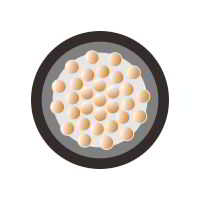
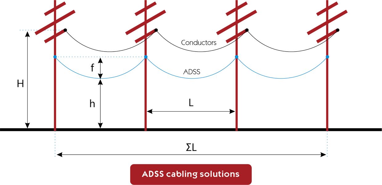
ADSS cables offer a cost-effective alternative to OPGW (Optical Ground Wire) and OPAC (Optical Phase Conductor) cables. They are engineered for strength, enabling installations spanning up to 700 meters between support towers. Their design focuses on being lightweight and having a small diameter to minimize the impact on tower structures from factors like cable weight, wind, and ice.
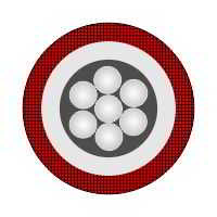
The cable's design ensures the internal glass optical fibers are supported with minimal strain, maintaining low optical loss over the cable's lifetime. A protective jacket shields the fibers from moisture and safeguards the cable's polymer strength components from solar UV radiation.
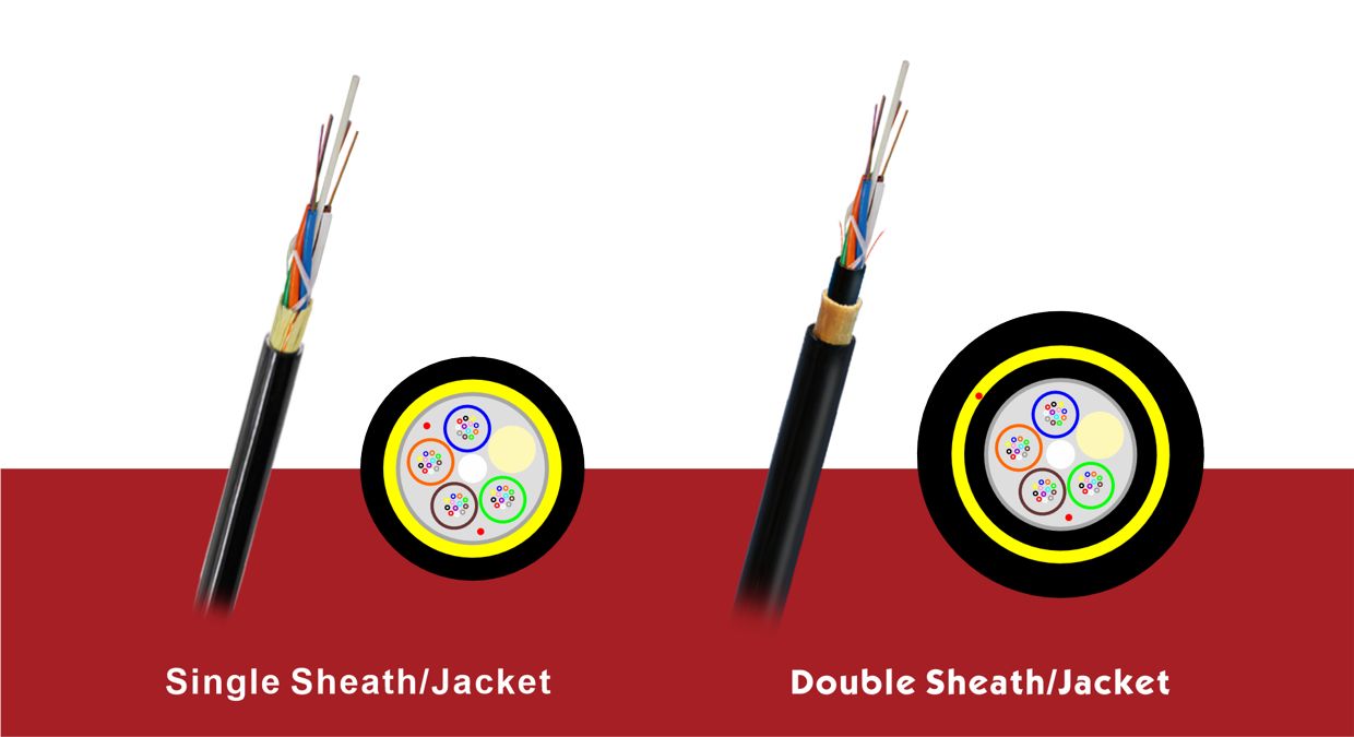
This type features a single outer jacket layer. Lightweight: It's typically lighter than double sheath variants.
Ideal for environments with lower risk of mechanical damage or where cable weight is a critical factor.
Generally more cost-effective due to less material usage.
Equipped with two layers of sheathing, an inner and an outer jacket.
Provides better mechanical protection, making it suitable for harsher environments.
More resistant to abrasion, rodents, and other forms of physical damage.
Heavier and typically more expensive than single sheath cables due to additional materials.
Short Span Aerial Installations:
Ideal for roadside power poles due to their lightweight, selfsupporting design.
Their non-metallic nature makes them safe for use close to highvoltage lines.
Employed in long-distance telecom networks, capable of supporting up to 100 km circuits without repeaters using single-mode fibers.
Used by power utilities for reliable communication within the power grid.
Military Use: Originally developed for military applications, they are still used for rapid deployment in field communications.
Span Length:
Choose based on the distance between support structures; Short spans like 80m, longer spans up to 700m.
Decide on the number of fibers(6,12,24,48,96,144) needed for your data transmission requirements.
Most popular is G.652.D Environmental Conditions: Consider factors like wind, ice, and UV exposure to determine the need for protective sheathing.
Ensure the cableʼs electrical characteristics are safe for installation near power lines.
Evaluate the cableʼs tensile strength and weight for installation and environmental stress resistance.
Balance strength with the limitations of installation and support structures.
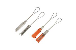
Preformed tension dead-end grip is usually used in the installation of the exposed conductor, electric transmission & distribution, and overheard insulated conductor. The reliability and economic advantage are better than the present bolt type and hydraulic
compression type Tension clamp Dead-end which now is being widely in the line. ADSS cable guy grips were developed to grip the ADSS fiber optical cable during the construction of internet network lines on wood poles or concrete towers.
ADSS suspension clamp is also called preformed suspension clamp or AGS suspension clamp, it offers a complete set of Aluminum clad, rubber, armor grip, bolt, and nut to support and protect the ADSS/OPGW cable from damage due to bending.
Stainless Steel strapping is ideal for ADSS cable and pipe banding applications that require various bundle diameters.
- Metal channel structural frame provides a durable light-weight design with ridged strength that is easy to install.
- Corrosion Resistant Materials - Aluminum.
- Bolt together Crossarm packs in the uniform low-profile container that reduces shipping costs and is easier to inventory.
- Multiple Keyholes adapt various Splice Cases.
- Wide cable keepers avoid point loads and provide better cable support.
Down-lead Clamp is designed to lead down cables on the splice and Terminal Poles/ towers and to fix the arch section on the Middle Reinforcing Poles/ towers.
Normally, a unit of Down-lead Clamp is needed per 1.5 meters, and it is also used in other fixing areas.
The cables are designed to be strong enough to allow lengths of up to 700 meters to be installed between support towers. ADSS cable is designed to be lightweight and small in diameter to reduce the load on tower structures due to cable weight, wind, and ice.
In the design of the cable, the internal glass optical fibers are supported with no strain to maintain low optical loss throughout the life of the cable. The cable is jacketed to prevent moisture from degrading the fibers.
The jacket also protects the polymer strength elements from the effect of solar ultraviolet light. Using single-mode fibers and light wavelengths of either 1310 or 1550 nanometres, circuits up to 100 km long are possible without repeaters.
A single cable can carry as many as 144 fibers.
ADSS cables made by ZION COMMUNICATION with 6,12,24,48,96 fibers range from 200 to 250 kg/kilometer and are between 11 and 17 mm outside jacket diameter. These cables can support between 4 TO 50 kilonewtons of tension.s determined.
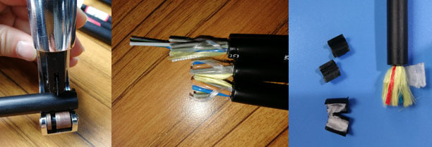
ADSS cable production process - Kevlar + outer sheath
In order to properly design the structure of the ADSS cable, many aspects must be considered, including mechanical strength, conductor sag, wind speed b ice thickness c temperature d topography, Span, and Voltage.
Usually, when you are in production, you need to consider the following questions.
Jacket Type: AT/PE
PE sheath: ordinary polyethylene sheath. For power lines below 110KV and ≤12KV electric field strength. The cable should be suspended where the electric field strength is small.
AT sheath: anti-tracking sheath. For power lines above 110KV, ≤20KV electric field strength. The cable should be suspended where the electric field strength is small.
Out Cable Dia.: Single Jacket 8mm-12mm; Double jacket 12.5mm-18mm
Fiber Count: 4-144Fibers
Aramid Yarn Details: Something like (20*K49 3000D). This main calculation of tensile strength.
According to the stress formula, S=Nmax/E*ε,
E (Tensile modulus)=112.4 GPa(K49 1140Dinner)
ε=0.8%
Usually designed strain<1%(Stranded Tube)UTS;
≤0.8%, evaluation
Nmax=W*(L2/8f+f);
L=span(m);usually 100m,150m,200m,300m,500m,600m;
f=Cable sag; usually 12m or 16m.
Nmax=W*(L2/8f+f)=0.7*(500*500/8*12+12)=1.83KN
S=Nmax/E*ε=1.83/114*0.008=2 mm²
Saramid(K49 2840D)=3160*10-4/1.45=0.2179mm²
N numbers aramid yarn=S/s=2/0.2179=9.2
General aramid fiber hinge pitch is 550mm-650mm,angle=10-12°
W=Maximum load (kg/m)=W1+W2+W3=0.2+0+0.5=0.7kg/m
W1=0.15kg/m(This is the weight of ADSS cable)
W2=ρ*[(D+2d)⊃2;-D⊃2;]*0.7854/1000(kg/m) (This is the weight of ICE)
ρ=0.9g/cm³, the density of ice.
D=Diameter of ADSS. Usually 8mm-18mm
d=Ice cover thickness;No ice=0mm,Light ice=5mm,10mm;Heavy ice=15mm,20mm,30mm;
Let's say the ice is thick is 0mm, W2=0
W3=Wx=α*Wp*D*L=α*(V⊃2;/1600)*(D+2d)*L/9.8 (kg/m)
Let's say the wind speed is 25m/s, α=0.85; D=15mm;W3=0.5kg/m
Wp=V⊃2;/1600 (Standard partial pressure formula, V means wind speed)
α= 1.0(v<20m/s);0.85(20-29m/s);0.75(30-34m/s);0.7(>35m/s) ;
α means Coefficient of the unevenness of wind pressure.
Level | phenomenon | m/s
1 Smoke can indicate the wind direction. 0.3 to 1.5
2 The human face feels windy, and the leaves move slightly. 1.6 to 3.3
3 The leaves and micro-techniques are shaking, and the flag is unfolding. 3.4~5.4
4 The floor dust and paper can be blown up, and the tree's twigs are shaken. 5.5 to 7.9
5 The small leafy tree sways and wavelets in the inland waters. 8.0 to 10.7
6 The big branches are shaking, the wires are vocal, and it is not easy to lift the umbrella. 10.8~13.8
7 The whole tree is shaken, and it is inconvenient to walk in the wind. 13.9~17. l
8 The micro-branch is broken, and people feel very resistant to moving forward. 17.2~20.7
9 The grass house was damaged, and the branches were broken. 20.8 to 24.4
10 Trees can be blown down, and general buildings are destroyed. 24.5 to 28.4
11 Rare on land, large trees can be blown down, and general buildings are severely damaged. 28.5~32.6
12 There are few on the land, and its destructive power is enormous. 32.7~36.9
RTS: Rated tensile strength
Refers to the calculated value of the strength of the bearing section (mainly counting the spinning fiber).
UTS: Ultimate Tensile Strength UES>60% RTS
In the effective life of the cable, it is possible to exceed the design load when the cable by the maximum tension. That means the cable can be overloaded for a short time.
MAT: Max allowable working tension 40% RTS
MAT is an essential basis for sag-tension-span calculation and necessary evidence to characterize the stress-strain characteristics of ADSS optical cable. Refers to the design of meteorological conditions under the theoretical analysis of the total load and cable tension.
Under this tension, the fiber strain should be no more than 0.05% (laminated) and no more than 0.1% (central pipe) without additional attenuation.
EDS: Every Day Strength (16~25)% RTS
The annual average stress, sometimes called the moderate daily stress, refers to the wind and no ice, and the yearly average temperature, the theoretical calculation of the load cable tension, can be considered the ADSS in the long-term operation of the intermediate pressure (should) force.
EDS is generally (16~25) %RTS.
Under this tension, the fiber should have no strain, no additional attenuation, that is, very stable.
EDS is also the fatigue aging parameter of optical fiber optic cable, according to which the anti-vibration design of optical fiber optic cable is determined.
5) 2 weeks before the completion of production, we will notify you to start contacting shipping.
All-Dielectric Self-Supporting (ADSS) cables are a type of optical fiber cable uniquely capable of selfsupporting installation between structures, eliminating the need for conductive metal elements. Commonly utilized by electrical utilities, these cables are installed alongside existing overhead transmission lines, often using the same supports as electrical conductors.
ADSS cables offer a cost-effective alternative to OPGW (Optical Ground Wire) and OPAC (Optical Phase Conductor) cables. They are engineered for strength, enabling installations spanning up to 700 meters between support towers. Their design focuses on being lightweight and having a small diameter to minimize the impact on tower structures from factors like cable weight, wind, and ice.
The cable's design ensures the internal glass optical fibers are supported with minimal strain, maintaining low optical loss over the cable's lifetime. A protective jacket shields the fibers from moisture and safeguards the cable's polymer strength components from solar UV radiation.
This type features a single outer jacket layer. Lightweight: It's typically lighter than double sheath variants.
Ideal for environments with lower risk of mechanical damage or where cable weight is a critical factor.
Generally more cost-effective due to less material usage.
Equipped with two layers of sheathing, an inner and an outer jacket.
Provides better mechanical protection, making it suitable for harsher environments.
More resistant to abrasion, rodents, and other forms of physical damage.
Heavier and typically more expensive than single sheath cables due to additional materials.
Short Span Aerial Installations:
Ideal for roadside power poles due to their lightweight, selfsupporting design.
Their non-metallic nature makes them safe for use close to highvoltage lines.
Employed in long-distance telecom networks, capable of supporting up to 100 km circuits without repeaters using single-mode fibers.
Used by power utilities for reliable communication within the power grid.
Military Use: Originally developed for military applications, they are still used for rapid deployment in field communications.
Span Length:
Choose based on the distance between support structures; Short spans like 80m, longer spans up to 700m.
Decide on the number of fibers(6,12,24,48,96,144) needed for your data transmission requirements.
Most popular is G.652.D Environmental Conditions: Consider factors like wind, ice, and UV exposure to determine the need for protective sheathing.
Ensure the cableʼs electrical characteristics are safe for installation near power lines.
Evaluate the cableʼs tensile strength and weight for installation and environmental stress resistance.
Balance strength with the limitations of installation and support structures.
Preformed tension dead-end grip is usually used in the installation of the exposed conductor, electric transmission & distribution, and overheard insulated conductor. The reliability and economic advantage are better than the present bolt type and hydraulic
compression type Tension clamp Dead-end which now is being widely in the line. ADSS cable guy grips were developed to grip the ADSS fiber optical cable during the construction of internet network lines on wood poles or concrete towers.
ADSS suspension clamp is also called preformed suspension clamp or AGS suspension clamp, it offers a complete set of Aluminum clad, rubber, armor grip, bolt, and nut to support and protect the ADSS/OPGW cable from damage due to bending.
Stainless Steel strapping is ideal for ADSS cable and pipe banding applications that require various bundle diameters.
- Metal channel structural frame provides a durable light-weight design with ridged strength that is easy to install.
- Corrosion Resistant Materials - Aluminum.
- Bolt together Crossarm packs in the uniform low-profile container that reduces shipping costs and is easier to inventory.
- Multiple Keyholes adapt various Splice Cases.
- Wide cable keepers avoid point loads and provide better cable support.
Down-lead Clamp is designed to lead down cables on the splice and Terminal Poles/ towers and to fix the arch section on the Middle Reinforcing Poles/ towers.
Normally, a unit of Down-lead Clamp is needed per 1.5 meters, and it is also used in other fixing areas.
The cables are designed to be strong enough to allow lengths of up to 700 meters to be installed between support towers. ADSS cable is designed to be lightweight and small in diameter to reduce the load on tower structures due to cable weight, wind, and ice.
In the design of the cable, the internal glass optical fibers are supported with no strain to maintain low optical loss throughout the life of the cable. The cable is jacketed to prevent moisture from degrading the fibers.
The jacket also protects the polymer strength elements from the effect of solar ultraviolet light. Using single-mode fibers and light wavelengths of either 1310 or 1550 nanometres, circuits up to 100 km long are possible without repeaters.
A single cable can carry as many as 144 fibers.
ADSS cables made by ZION COMMUNICATION with 6,12,24,48,96 fibers range from 200 to 250 kg/kilometer and are between 11 and 17 mm outside jacket diameter. These cables can support between 4 TO 50 kilonewtons of tension.s determined.
ADSS cable production process - Kevlar + outer sheath
In order to properly design the structure of the ADSS cable, many aspects must be considered, including mechanical strength, conductor sag, wind speed b ice thickness c temperature d topography, Span, and Voltage.
Usually, when you are in production, you need to consider the following questions.
Jacket Type: AT/PE
PE sheath: ordinary polyethylene sheath. For power lines below 110KV and ≤12KV electric field strength. The cable should be suspended where the electric field strength is small.
AT sheath: anti-tracking sheath. For power lines above 110KV, ≤20KV electric field strength. The cable should be suspended where the electric field strength is small.
Out Cable Dia.: Single Jacket 8mm-12mm; Double jacket 12.5mm-18mm
Fiber Count: 4-144Fibers
Aramid Yarn Details: Something like (20*K49 3000D). This main calculation of tensile strength.
According to the stress formula, S=Nmax/E*ε,
E (Tensile modulus)=112.4 GPa(K49 1140Dinner)
ε=0.8%
Usually designed strain<1%(Stranded Tube)UTS;
≤0.8%, evaluation
Nmax=W*(L2/8f+f);
L=span(m);usually 100m,150m,200m,300m,500m,600m;
f=Cable sag; usually 12m or 16m.
Nmax=W*(L2/8f+f)=0.7*(500*500/8*12+12)=1.83KN
S=Nmax/E*ε=1.83/114*0.008=2 mm²
Saramid(K49 2840D)=3160*10-4/1.45=0.2179mm²
N numbers aramid yarn=S/s=2/0.2179=9.2
General aramid fiber hinge pitch is 550mm-650mm,angle=10-12°
W=Maximum load (kg/m)=W1+W2+W3=0.2+0+0.5=0.7kg/m
W1=0.15kg/m(This is the weight of ADSS cable)
W2=ρ*[(D+2d)⊃2;-D⊃2;]*0.7854/1000(kg/m) (This is the weight of ICE)
ρ=0.9g/cm³, the density of ice.
D=Diameter of ADSS. Usually 8mm-18mm
d=Ice cover thickness;No ice=0mm,Light ice=5mm,10mm;Heavy ice=15mm,20mm,30mm;
Let's say the ice is thick is 0mm, W2=0
W3=Wx=α*Wp*D*L=α*(V⊃2;/1600)*(D+2d)*L/9.8 (kg/m)
Let's say the wind speed is 25m/s, α=0.85; D=15mm;W3=0.5kg/m
Wp=V⊃2;/1600 (Standard partial pressure formula, V means wind speed)
α= 1.0(v<20m/s);0.85(20-29m/s);0.75(30-34m/s);0.7(>35m/s) ;
α means Coefficient of the unevenness of wind pressure.
Level | phenomenon | m/s
1 Smoke can indicate the wind direction. 0.3 to 1.5
2 The human face feels windy, and the leaves move slightly. 1.6 to 3.3
3 The leaves and micro-techniques are shaking, and the flag is unfolding. 3.4~5.4
4 The floor dust and paper can be blown up, and the tree's twigs are shaken. 5.5 to 7.9
5 The small leafy tree sways and wavelets in the inland waters. 8.0 to 10.7
6 The big branches are shaking, the wires are vocal, and it is not easy to lift the umbrella. 10.8~13.8
7 The whole tree is shaken, and it is inconvenient to walk in the wind. 13.9~17. l
8 The micro-branch is broken, and people feel very resistant to moving forward. 17.2~20.7
9 The grass house was damaged, and the branches were broken. 20.8 to 24.4
10 Trees can be blown down, and general buildings are destroyed. 24.5 to 28.4
11 Rare on land, large trees can be blown down, and general buildings are severely damaged. 28.5~32.6
12 There are few on the land, and its destructive power is enormous. 32.7~36.9
RTS: Rated tensile strength
Refers to the calculated value of the strength of the bearing section (mainly counting the spinning fiber).
UTS: Ultimate Tensile Strength UES>60% RTS
In the effective life of the cable, it is possible to exceed the design load when the cable by the maximum tension. That means the cable can be overloaded for a short time.
MAT: Max allowable working tension 40% RTS
MAT is an essential basis for sag-tension-span calculation and necessary evidence to characterize the stress-strain characteristics of ADSS optical cable. Refers to the design of meteorological conditions under the theoretical analysis of the total load and cable tension.
Under this tension, the fiber strain should be no more than 0.05% (laminated) and no more than 0.1% (central pipe) without additional attenuation.
EDS: Every Day Strength (16~25)% RTS
The annual average stress, sometimes called the moderate daily stress, refers to the wind and no ice, and the yearly average temperature, the theoretical calculation of the load cable tension, can be considered the ADSS in the long-term operation of the intermediate pressure (should) force.
EDS is generally (16~25) %RTS.
Under this tension, the fiber should have no strain, no additional attenuation, that is, very stable.
EDS is also the fatigue aging parameter of optical fiber optic cable, according to which the anti-vibration design of optical fiber optic cable is determined.
5) 2 weeks before the completion of production, we will notify you to start contacting shipping.