Author: James Publish Time: 12-01-2022 Origin: Site
Optical fiber drop cable, often referred to as FTTH (Fiber to the Home) cable, is the last segment in the fiber optic network, which connects the user's home/building terminal to the backbone cable terminal of an ISP provider. It lies at the end-user side and is necessary when FTTH (Fiber to the Home) is considered as accessing high-speed internet.
The cable is noted for its small size, low fiber count (1 to 4 fibers), and about 80 meters support span. It is the best applicable in overhead and duct installations, but it is inapt for underground and direct-burial installations.
The ISP employs drop cables to make a direct connection from the distribution point to the user's terminal devices or equipment. Usually, these cables contain up to 12 fibers, and it is common to treat them as coated-type fibers (for example, when color codes are applied for easy identification, such as blue, orange, green, brown, gray, etc.)
The outer sheath is generally composed of LSZH materials to satisfy the conditions of flame-retardancy and environmental friendliness in the indoor environment. The outer drop cables are designed with the additional elements providing water-blocking features and generally exotic protection for external environments.
Compact size and lightweight
Exceptional bending abilities and flexibility
Straightforward structure, which helps out with an easy setup
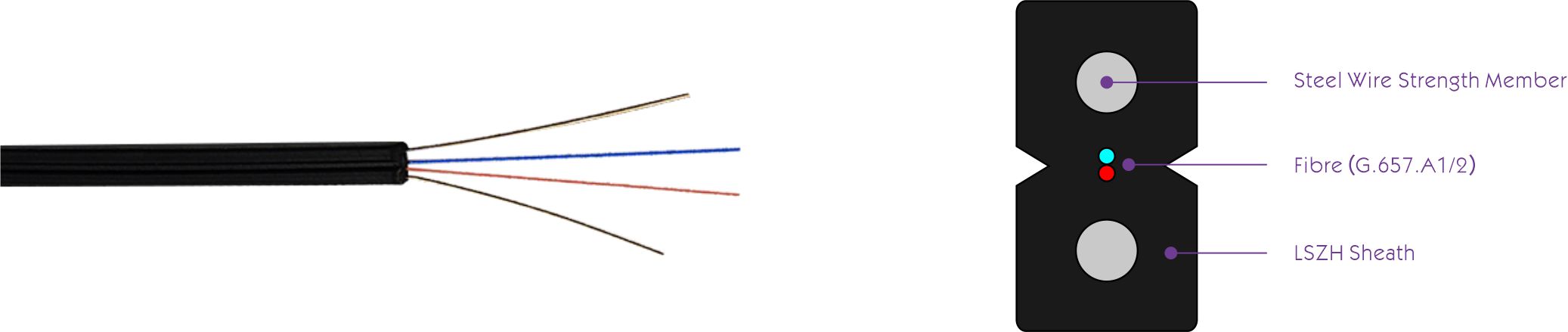
Very strong tensile strength, either held by parallel FRP or steel
Unique groove shape helps here in fiber stripping and terminations
LSZH (Low-Smoke, Zero-Halogen) jacket for indoor usage
The water-banned and UV-resistant construction is mandated for outdoor usage durability.
Indoor optical cables mainly include 1F, 2F, and 4F.
Household optical cables should use 1F;
Enterprise users should use 2-4F optical cable design.
There are two types of household optical cables:
FRP reinforcement and steel wire reinforcement.
Taking into account factors such as lightning protection and strong current interference, FRP reinforcement should be used indoors.
Wiring in buildings Horizontal wiring does not have high requirements for optical cables, while vertical wiring requires optical cables to have a certain tensile strength, as well as flame retardant requirements. Therefore, the tensile strength of optical cables must be considered.
The figure-8 self-supporting optical cable adds a steel wire suspension on the optical cable, offers more tensile strength, and can be laid overhead. It is suitable for outdoor overhead wiring to enter the indoor wiring environment. Before fixing the steel hanging wire on the special bracket, first cut off the steel wire, strip off the steel wire cable on the remaining optical cable.
Duct optical cables and self-supporting "8" optical cables are both indoor and outdoor integrated optical cables, which can adapt to indoor and outdoor environments, and are suitable for FTTH drop cable from outside to indoor. Because the outer sheath, reinforcement, and water-blocking materials are added on the drop optical fiber cable, the Duct optical cable has higher hardness and waterproof performance and is suitable for outdoor duct laying.
Internet service providers connect directly to service equipment by using optical cables. Usually contains no more than 12 fibers. The following four fiber optic cable designs are the most commonly used today.
FTTH optical cable (known as drop cable). The drop flat cable contains 1 to 4 coated ptical fibers. The coating of the optical fiber can be colored, blue, orange, green, brown, gray, white, red, black, yellow, purple, pink or light green in compliance with the requirements.
The single-fiber use natural color. The reinforcement in the cable can be steel wire , or FRP reinforcement. The sheath of the drop cable should be made of low-smoke and zero-halogen materials to meet environmental protection and flame-retardant indoor wiring requirements. Outdoor FTTH drop cables should meet the water-blocking requirements.
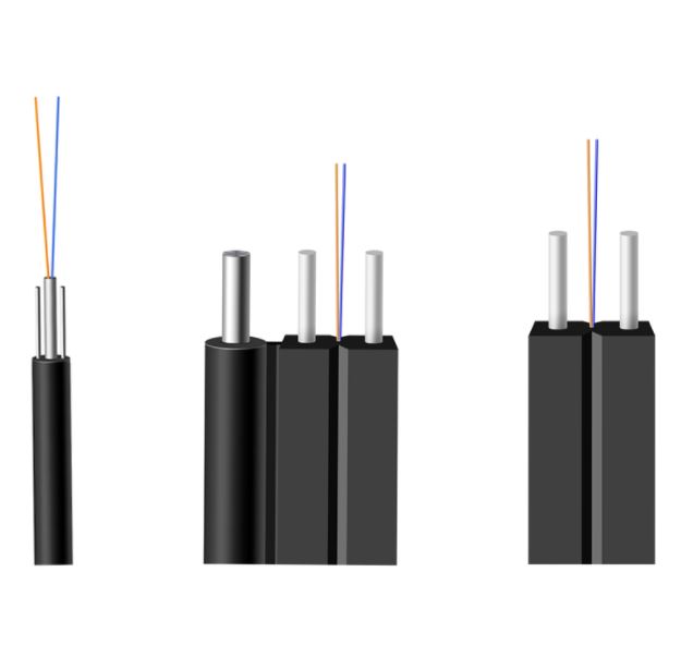
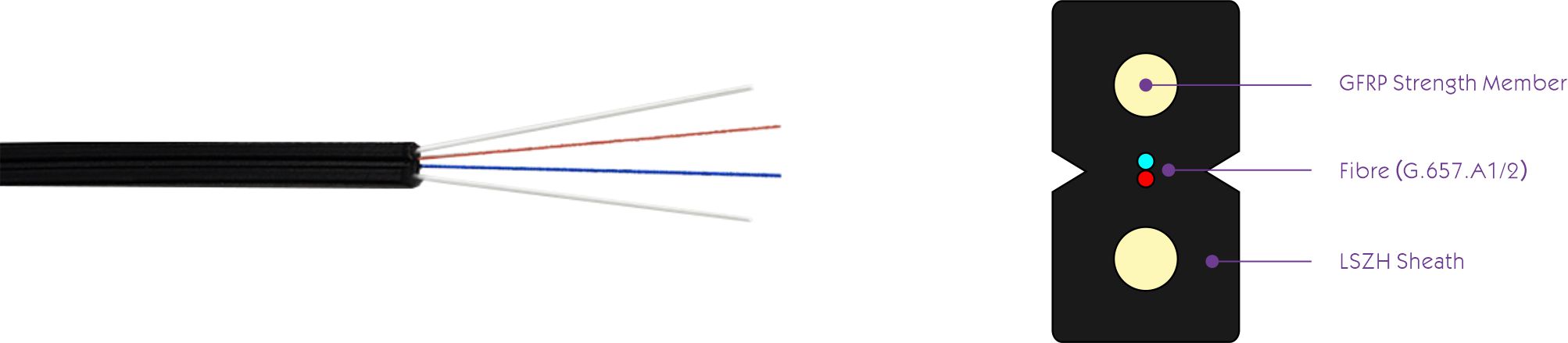
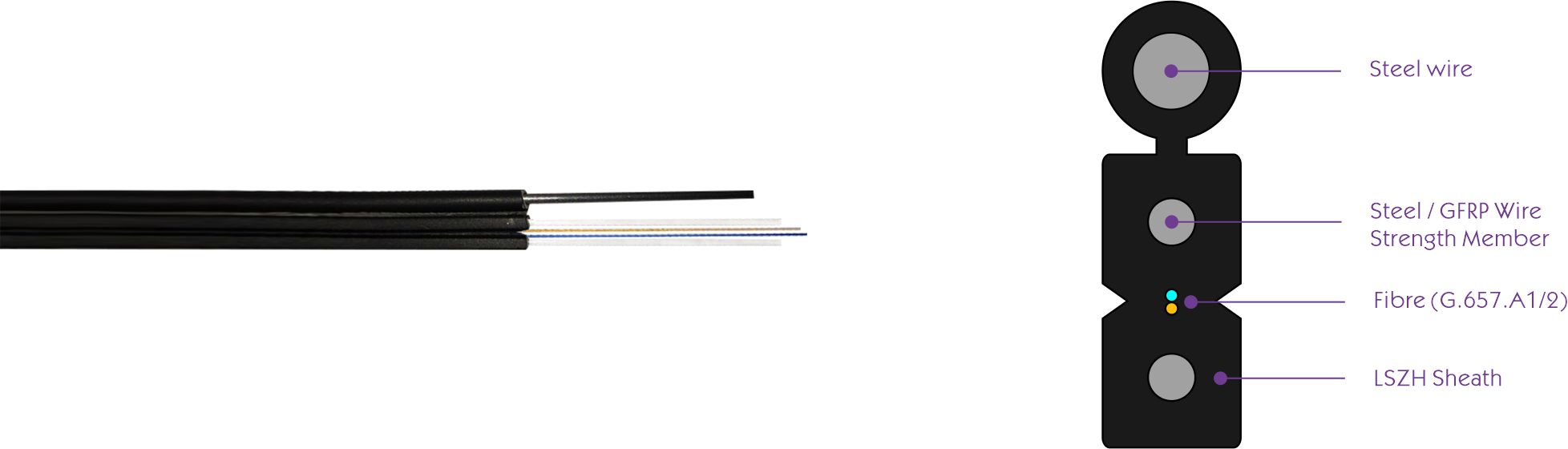
Contains two longitudinal FRP or steel wires reinforced with 1F/2F/4F fibers
FRP reinforcements are recommended for indoors to prevent the interference of electricals and ensure insulation.
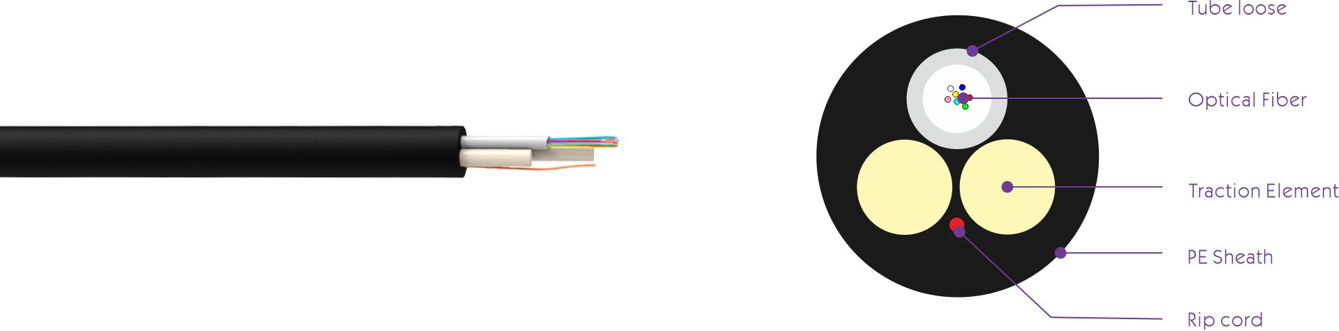
Outdoor Flat Steel Drop Cable GJXH
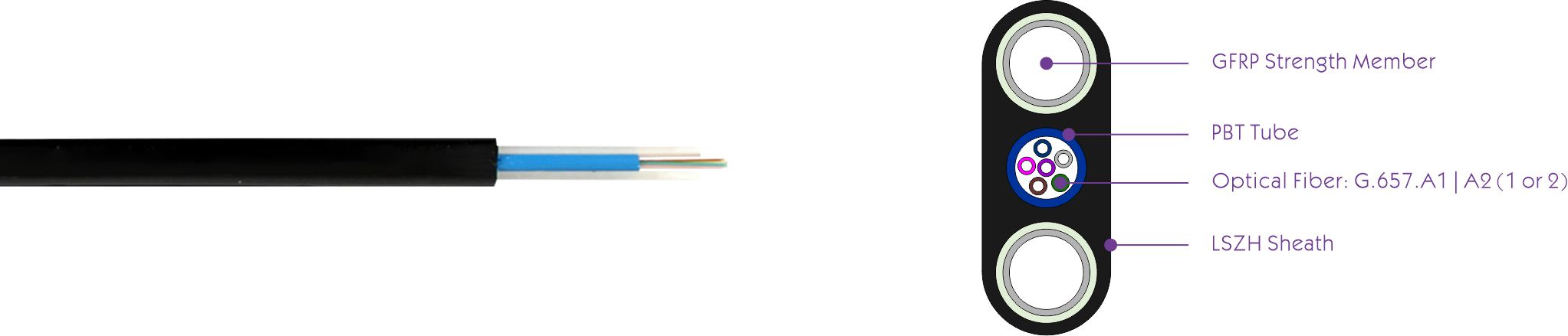
Flat and compact figure-8 called mini figure-8
With the incorporation of water-banning materials and sheath, durable ones
Most applicable for aerial installations and overhead ducting
Outdoor Self-Supporting Figure-8 Steel Drop Cable GJYXCH
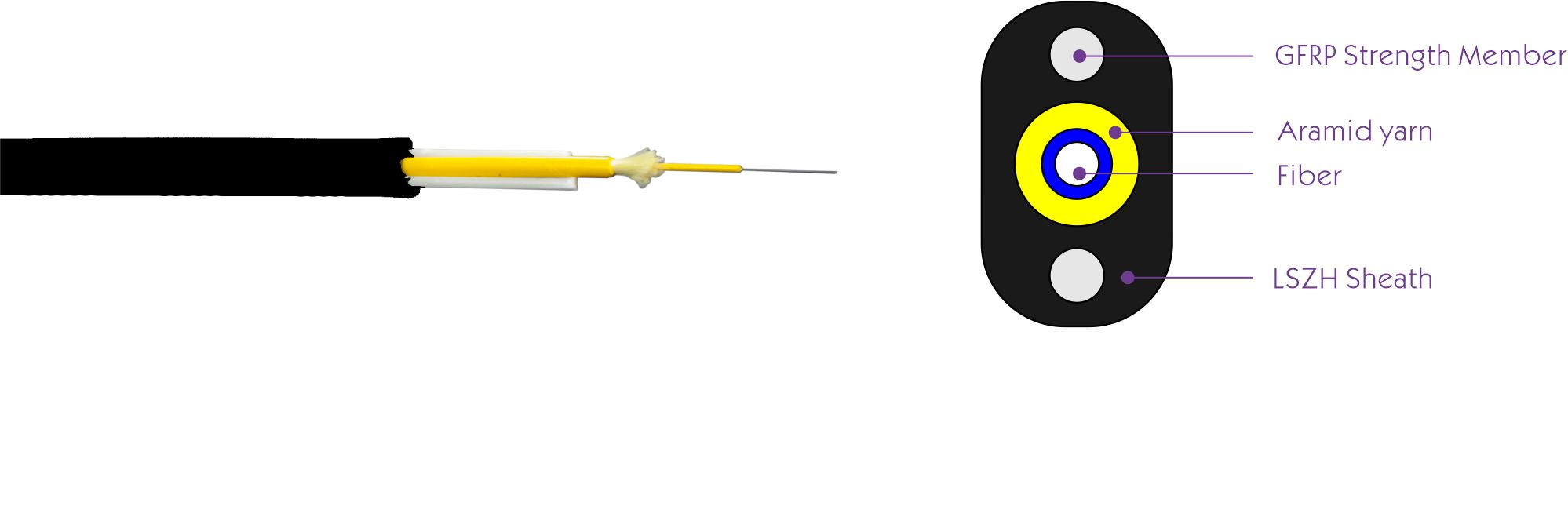
FTTH (Fiber to the Home) and indoor wiring
Pre-terminated in the factory
More suitable for optical fiber connection and fast connector
Fiber to the home(FTTH)
Office Building
PC room
Fiber to the home(FTTH)
Office Building
PC room
Figure-8 aerial drop cable is self-supporting cable, with the cable fixed to a steel wire, designed for easy and economical aerial installation for outdoor applications.
This type of fiber drop cable is fixed to a steel wire as showed in the following picture.
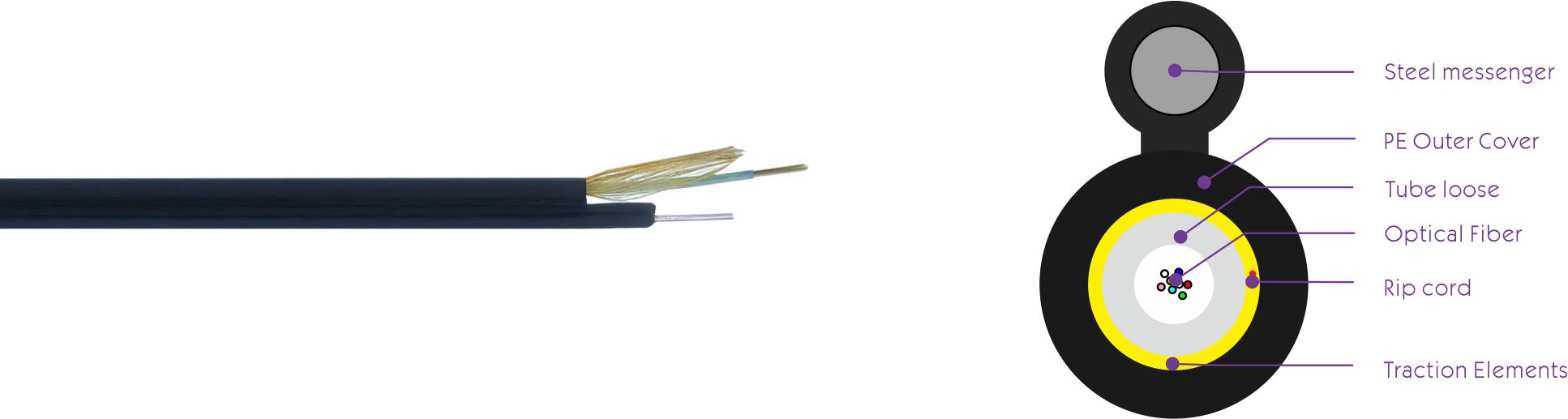
Armored Duct/Aerial Drop Cable GYXTW
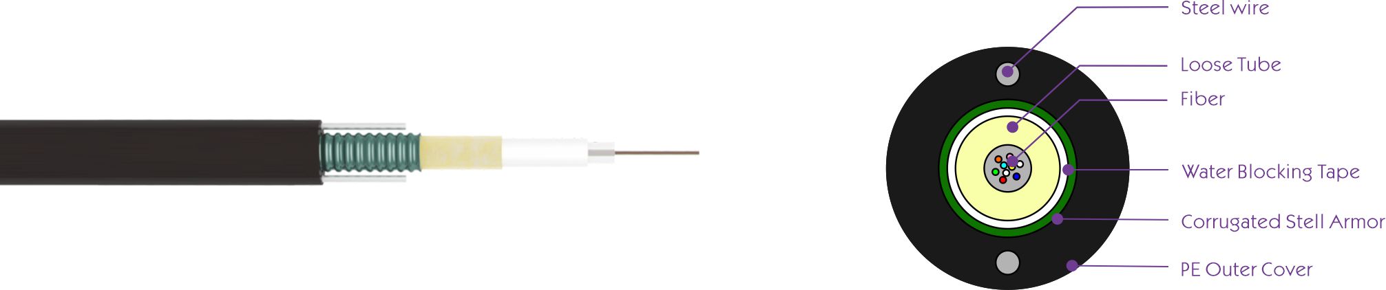
The communication between the office, metropolitan area network, and access network is especially suitable for occasions that require high-density optical fibers. Laying method: Aerial & Conduit
Rural communications, local trunk lines, cable television and computer network systems, long-distance communications and local area networks
Self-supporting Air Installations;
Fully dielectric, does not need to be grounded;
Ideal for outdoor applications up to 120 m without messenger;
Available with normal polyethylene (NR) and flame retardant (RC) cover;
Adopted to Outdoor distribution
Network in high electromagnetic interfering places
Suitable for aerial network
Zion Communication is one of the top manufacturers and exporters of Fiber optic cables from China, and also we are your best choice of partner in this field. In the past 10 years, we have been providing high quality products to telecom operators, ISPs, trade importers, OEM customers and various communication projects in more than 100 countries around the world.
Zion Communication focuses on optical fiber OEM production services, and is committed to providing customers with brand customization, personalized packaging design, optimal cable structure design, and the best packaging design for international container transportation.
Optical fiber cables include ADSS cables, FTTH flat drop cables, Aerial installation cables, Duct installation cables, Direct buried installation cables, Air blowing installation cables, Biological protection cables, etc.
As well as a variety of fiber optic cable according to the customer's use scenario, provide a variety of fiber optic cable structure design and manufacturing.
Correct and excellent structural design.
The best match of a dozen raw materials is combined.
Experienced and excellent production technology.
Unique protective packaging design for international transportation.
We use self-developed structural software, design the structure of the cable, follow with the international standard design premise, try to optimize the product structure.
For the cable structure design, in addition to the customer specified structure. According to the customer's cable usage scenario, we will ask engineers to specially design three optimal structures, and provide customers with three suggestions and choices. In view of the increasingly fierce competition, make high, middle and low three schemes to ensure that customers win orders.
For example, for the Main Specifications of ADSS,
Optical fiber is the foundation to ensure cable communication, we will choose 3 brands of world famous optical fiber.
In addition to the above 3 brands, we selected the largest fiber optic factories in China, and also guaranteed the quality.
We will test for multiple data include attenuation indicators of the fiber. Guaranteed fiber Meet ITU-T ;
Dimensions: 9/125/250±5μm
Recommended Band
O: 1260-1360(Zero Dispersion Wavelength) 1310nm
C: 1530-1565 (Minimum attenuation) 1550nm
Core / Cladding Concentricity Error≤0.4μm (0.7%)
Attenuation Coefficient : @1310; 1550nm≤0.35;0.21dB/km
Mode Field Diameter : @1310; 1550nm≤8.6±0.4;9.8±0.4μm
Point Discontinuity : @1310; 1550nm≤0.05dB
Cable Cut-off wavelength(λ cc) : ≤1260nm
Fiber Strain : ≥1% ; Fiber Load≥9N
Temperature Cycling(-60℃~+85℃) : ≤0.05dB/km
Macro Bending Loss : 100turns of 30mm radius≤0.05 All materials use High-Quality raw materials :
Optical Fibers : All Performance Meets ITU-T Technical Standards
Tube Filling : Thixotropic Gel Compound
Loose Tube : Polybutyleneterephthalate(PBT)
Central Dielectric Strength Member : Fiberglass Reinforced Plastic(G-FRP)
Filler : Polypropylene(PP) with the same Diameter as Tubes
Waterblocking Yarn : Polyester filament, polymer expandable water absorbent resin
Water Swellable Tape : Polyester non-woven fabric, super absorbent resin, adhesive
Binder : Polyethylene Terephthalate(Polyester Yarn)
Ripcord : High strength tear rope
Dielectric Strength Member : Aramid Yarn1414, Para-Aramid Fiber Yarn (PPTA) poly- p- phenylene terephthamide, Tensile modulus ≥120Gpa
Outer Jacket : High Density Poly Ethylene (HDPE)
Typically, the price per fiber optic cable ranges from $30 to $1000, depending on the type and quantity of fibers: G657A1/G657A2/G652D/OM2/OM3/OM4/OM5, jacket material PVC/LSZH/PE, length, and Structural design and other factors affect the pricing of drop cables.
Fiber optic cables are often classified as fragile, just like glass. Of course, the fiber is glass. The glass fibers in fiber optic cables are fragile, and while fiber optic cables are designed to protect the fibers, they are more prone to damage than copper wire. The most common damage is fiber breakage, which is difficult to detect. However, fibers can also break due to excessive tension during pulling or breaking.
Fiber optic cables are usually damaged in one of two ways:
• Prefabricated fiber optic cables may damage the connectors if excessive tension is applied during installation.
This can happen when long fiber optic cables are passed through tight conduits or ducts or when fiber optic cables get stuck.
• The fiber optic cable was cut or broken during operation and needed to be re-spliced to reconnect.
If you can see a lot of red lights, the connector is terrible and should be replaced. The connector is good if you look at the other end and only see the light from the fiber. It's not good if the whole ferrule is glowing. The OTDR can determine if the connector is damaged if the cable is long enough.
The bend radius of the fiber optic cable is critical for installation. Factors that affect the minimum radius of a fiber optic cable include outer jacket thickness, material ductility, and core diameter. To protect the integrity and performance of the cable, we cannot bend it beyond its allowable radius. In general, if bend radius is a concern, bend-insensitive fiber is recommended, allowing easy cable management and reducing signal loss and cable damage when the cable is bent or twisted. Below is the bend radius chart.
Fiber Cable Type | Minimum Bend Radius |
G652D | 30mm |
G657A1 | 10mm |
G657A2 | 7.5mm |
B3 | 5.0mm |
Send the light signal into the cable. When doing this, look carefully at the other end of the cable. If the light is detected in the core, it means the fiber is not broken, and your cable is fit for use.
For about 30 years, for properly installed fiber cables, the probability of failure in such a time frame is about 1 in 100,000.By comparison, the chance of human intervention (such as digging) damaging the fiber is about 1 in 1,000 over the same time. Therefore, under acceptable conditions, a high-quality fiber with good technology and careful installation should be very reliable - as long as it is not disturbed.
When the temperature drops below zero and the water freezes, ice forms around the fibers - which causes the fibers to deform and bend. This then reduces the signal through the fiber, at least reducing the bandwidth but most likely stopping data transmission altogether.
The most common causes of fiber failures:
• Fiber breakage due to physical stress or excessive bending
• Insufficient transmit power
• Excessive signal loss due to long cable spans
• Contaminated connectors can cause excessive signal loss
• Excessive signal loss due to connector or connector failure
• Excessive signal loss due to connectors or too many connectors
• Incorrect connection of fiber to patch panel or splice tray
Usually, if the connection fails completely, it's because the cable is broken.
However, if the connection is intermittent, there are several possible reasons:
• Cable attenuation may be too high due to poor quality connectors or too many connectors.
• Dust, fingerprints, scratches, and moisture can contaminate connectors.
• Transmitter strength is low.
• Poor connections in the wiring closet.
Cable Depth: The depth to which buried cables can be placed will vary depending on local conditions, such as "freeze lines" (the depth to which the ground freezes each year). It is recommended to bury fiber optic cables to a deep/coverage of at least 30 inches (77 cm).
The best way to locate a fiber optic cable is to insert the cable pole into the conduit, then use an EMI locating device to connect directly to the cable pole and track the signal, which, if done correctly, can provide a very accurate location.
As we all know, the cost of damaging live fiber optic cables is high. They usually carry a hefty load of communications. It is imperative to find their exact location.Unfortunately, they are challenging to locate with ground scans. They're not metal and can't use steel with a cable locator. The good news is that they are usually bundled together and may have external layers. Sometimes, they are easier to spot using ground-penetrating radar scans, cable locators, or even metal detectors.
Buffer tubes are used in fiber optic cables to protect fibers from signal interference and environmental factors, as they are commonly used in outdoor applications. Buffer tubes also block water, which is especially important for 5G applications because they are used outdoors and are often exposed to rain and snow. If water gets into the cable and freezes, it can expand inside the cable and damage the fiber.
Types of Splicing
There are two splicing methods, mechanical or fusion. Both ways offer much lower insertion loss than fiber optic connectors.
Mechanical splicing
Optical cable mechanical splicing is an alternative technique that does not require a fusion splicer. Mechanical splices are splices of two or more optical fibers that align, and the components that keep the fibers aligned are placed using an index-matching fluid. Mechanical splicing uses minor mechanical splicing approximately 6 cm in length and about 1 cm in diameter to permanently connect two fibers. This precisely aligns the two bare fibers and then mechanically secures them. Snap-on covers, adhesive covers, or both are used to secure the splice permanently. The fibers are not permanently connected but are joined together so that light can pass from one to the other. (insertion loss <0.5dB)Splice loss is typically 0.3 dB. However, fiber mechanical splicing introduces higher reflections than fusion splicing methods. The optical cable mechanical splice is small, easy to use, and convenient for quick repair or permanent installation. They have permanent and re-enterable types. Optical cable mechanical splices are available for single-mode or multi-mode fiber.
Fusion splicing
Fusion splicing is more expensive than mechanical splicing but lasts longer. The fusion splicing method fuses the cores with less attenuation. (insertion loss <0.1dB)During the fusion splicing process, a dedicated fusion splicer is used to align the two fiber ends precisely, and then the glass ends are "fused" or "welded" together using an electric arc or heat. This creates a transparent, non-reflective, continuous fiber connection, enabling low-loss optical transmission. (Typical loss: 0.1 dB)The fusion splicer performs optical fiber fusion in two steps.
1. Precise alignment of the two fibers
2. Create a slight arc to melt the fibers and weld them together. In addition to the typically lower splice loss of 0.1dB, the benefits of splice include fewer back reflections.
Typical insertion loss for single-mode mechanical connectors ranges from 0.05 to 0.2 dB. Fiber splicing is one of the most widely used permanent methods of connecting optical fibers.
Fiber cables can be divided into indoor and outdoor according to different use environments.The indoor optical cable is a kind of optical cable formed by optical fiber (optical transmission carrier) through a specific process. It mainly consists of optical fibers (glass filaments as thin as hair), plastic protective sheaths, and plastic casings. There is no gold, silver, copper, or aluminum in the optical cable, and it generally has no recycling value.The indoor optical cable is a kind of communication line that is formed by a certain number of optical fibers in a certain way, and some are wrapped with a sheath or an outer sheath to realize optical signal transmission. Indoor fiber optic cables have low tensile strength and poor protection but are more portable and economical. Indoor optical cables are mainly used for building wiring connections between network equipment.
Indoor optical cables have low tensile strength and a poorer protective layer but are relatively light and more economical. They are mainly suitable for horizontal wiring and backbone subsystems. Outdoor optical cables have higher tensile strength and a thicker protective layer and are generally packaged with armor. They are primarily used in building complex subsystems and can be used for occasions such as outdoor burial, pipeline, overhead and underwater laying, and other events.
Outdoor optical cables are optical cables for outdoor use. The comparison is the indoor optical cable. Outdoor optical cables are communication lines used for optical signal transmission.A certain number of optical fibers form a cable core in a certain way, with an inner jacket and an outer jacket.
It mainly consists of optical fibers (glass filaments as thin as hair), plastic protective sheaths, and plastic casings. The optical cable does not contain gold, silver, copper, or aluminum, and it generally has no recycling value. Outdoor optical cables have higher tensile strength and thicker protective layers and are usually armored (that is, covered with metal skin). Outdoor fiber optic cables are mainly used for interconnection between buildings and remote networks.
ADSS cable stands for All-Dielectric Self-Supporting cable. It is a type of optical fiber cable that is used in overhead transmission line installations. Unlike traditional transmission cables that are supported by metal wires or poles, ADSS cables are made of optical fibers and are self-supporting, meaning they do not require any external support structure. This makes them ideal for use in areas where it is difficult or impossible to install metal support structures, such as in wetlands or over water.
FTTH drop cable stands for Fiber to the Home drop cable. It is a type of optical fiber cable that is used to connect a home or building to a fiber optic network. FTTH drop cables typically consist of a single optical fiber that is surrounded by protective materials and enclosed in a durable outer jacket. The cable is typically installed by attaching one end to a fiber optic terminal box outside the home or building and running the other end through an entry point, such as a window or wall, into the building. From there, the fiber optic cable can be connected to an optical network terminal (ONT) inside the building, which allows devices inside the building to access the fiber optic network. FTTH drop cables are commonly used in broadband and telecommunications applications.
Aerial installation is a method of installing fiber optic cable by suspending it from poles or other overhead structures. This type of installation is commonly used in areas where it is not feasible to bury the cable underground, such as in mountainous or urban areas. In an aerial installation, the fiber optic cable is attached to poles or other structures using clamps, brackets, or other specialized hardware. The cable is then typically strung between poles or other structures using specialized equipment, such as a bucket truck or a helicopter.
Direct Buried Installation is a way to install an optical fiber cable directly into the ground. This type of device is often used where aerial suspension or duct installation is impossible.In a direct-buried installation, the fiber optic cable is generally buried at least 24 inches beneath the surface to protect it from potential damage. The cable is typically buried using special equipment, such as a cable plow or a trencher. Proper installation techniques and materials, such as backfilling and sand, are essential to ensure adequate protection and operation of cables.
Air-blown micro fiber optic cable is a fiber optic cable designed for use in air-blown fiber optic systems. These systems use compressed air to blow small-diameter fiber optic cables through tubes or ducts, allowing them to be quickly and easily installed without requiring specialized equipment or labor-intensive techniques. Air-blown micro fiber optic cable typically has a small diameter, less than 1 mm, and is made of a flexible material, such as plastic or rubber. This allows it to be easily blown through tubes or ducts and bent around corners or other obstacles. Air-blown micro fiber optic cable is commonly used in telecommunications and broadband applications.
Cabling in buildings refers to installing fiber optic cable in a building or other structure to provide connectivity for telecommunications and networking applications. In most cases, building cabling involves running the fiber optic cable through the building's walls, ceilings, and floors to connect various rooms and spaces. This can be done using various installation methods, such as aerial installation, duct installation, or direct buried installation. The specific method used will depend on the layout of the building and the available infrastructure.
Class | Strength member | Structural features | Sheath | Outer sheath | Fibre type |
GY-Outdoor | (void)-metallic | D-Fibre ribbon | Y-PE Sheath | 33-Steel wires armor+PE | B1-G652 |
GL-Micro trench | F-FRP | G-Slotted core | A-Aluminum Tape+PE | 53-Steel tape armor+PE | B1.3-G652D |
GP-Sewer | H-Aramid yarns | X-Uni-tube | S-Steel tape+PE | 54-Steel tape armor+PE+nylon sheath | B4-G655 |
G-Glass fibre yarns | T-Compound Filled | W-Steel tape+PE+2Steel wires | 63-Glass fibre yarn armor+PE | B6-G657 | |
A-Aramid yarns | (void)-Dry water blocking | F-Glass fibre tape+PE | 333-Double steel wire armor+PE | B6a2-G657A2 | |
C-Self-supporting | A1a-50/125μm | ||||
Z-Flame-retardant | A1b-62.5/125μm | ||||
B-Flat shape | |||||
8-Figure 8 |
Class | Strength member | Structural features | Sheath | Fibre type |
GJX-Indoor Wiring | (void)-metallic | D-Fibre ribbon | H-LSZH | B6-G657 |
GJYX-Outdoor Drop | F-FRP | C-Self-supporting | B6a2-G657A2 |
Class | Application Scope | Strength member | Structural features | Sheath | Fibre type |
GJ-Indoor | B-Branch | F-Non Metallic | J-Tigh buffer | H-LSZH | B1.3-G652D |
P-Bundle | B-Flat shape | V-PVC | B4-G655 | ||
D-Ribbon | U-PU | B6-G657 | |||
B6a2-G657A2 |
Type | FTTH | Metropolitan Area Network | Backbone Network | ||||||||||
Drop | Distribution | Feeder | |||||||||||
Duct | Aerial | S-S | Duct | Aerial | S-S | U-W | Buried | Aerial | S-S | U-W | |||
ADSS-SJ | √ | √ | √ | √ | |||||||||
ADSS-DJ | √ | √ | √ | √ | |||||||||
GJXH | √ | ||||||||||||
GJXFH | √ | ||||||||||||
GJYXCH | √ | √ | |||||||||||
GJYXFCH | √ | √ | |||||||||||
GJXDH | √ | ||||||||||||
GJXFDH | √ | ||||||||||||
GJYXDCH | √ | ||||||||||||
GJYXFDCH | √ | ||||||||||||
GJYXFHA | √ | √ | √ | ||||||||||
GJYXFHS | √ | √ | √ | ||||||||||
GJYXFH53 | √ | √ | √ | ||||||||||
GYTA | √ | √ | √ | √ | √ | ||||||||
GYTS | √ | √ | √ | √ | √ | ||||||||
GYFS | √ | √ | √ | √ | √ | ||||||||
GYTY53 | √ | √ | √ | ||||||||||
GYFY53 | √ | √ | √ | ||||||||||
GYTS54 | √ | √ | √ | √ | √ | ||||||||
GYTA53 | √ | √ | √ | ||||||||||
GYTS53 | √ | √ | √ | ||||||||||
GYTA33/333 | √ | √ | √ | √ | |||||||||
GYTS33/333 | √ | √ | √ | √ | |||||||||
GYTA53+33/333 | √ | √ | √ | √ | |||||||||
GYFTY | √ | √ | √ | √ | √ | ||||||||
GYFTA(S) | √ | √ | √ | √ | √ | ||||||||
GYFTY63 | √ | √ | √ | √ | √ | √ | √ | ||||||
GYFY63 | √ | √ | √ | √ | √ | √ | √ | ||||||
GYFTA53 | √ | √ | √ | ||||||||||
GYXTY | √ | √ | √ | √ | √ | ||||||||
GYFXTY | √ | √ | √ | √ | √ | ||||||||
GYXTW | √ | √ | √ | √ | √ | ||||||||
GYDTA | √ | √ | √ | √ | √ | √ | |||||||
GYDXTW | √ | √ | √ | √ | √ | √ | |||||||
GYTC8A(S) | √ | √ | |||||||||||
GYFTC8A(S) | √ | √ | |||||||||||
GYFC8Y | √ | √ | |||||||||||
GYFC8Y53 | √ | ||||||||||||
GYXTC8A(S) | √ | √ |
Color Arrangement of Fibres and Loose Tube
Standard Fibre Color Sequence, which complies with Standard TIA/EIA-598-2014.
Fibers Color Standard Sequence | ||||||
No. | 1 | 2 | 3 | 4 | 5 | 6 |
Color | Blue | Orange | Green | Brown | Gray | White(Natural) |
No. | 7 | 8 | 9 | 10 | 11 | 12 |
Color | Red | Black | Yellow | Violet | Pink | Aqua |
Note:
1. If there are less than 12 fibers in a loose tube, the color sequence is followed continuously, starting from No.1,
2. In the standard color sequence, No.6 white color can be replaced by natural color, called the W color sequence.
3. Color arrangement can be customized.
Tubes Color Standard Sequence | ||||||
No. | 1 | 2 | 3 | 4 | 5 | 6 |
Color | Blue | Orange | Green | Brown | Gray | White(Natural) |
No. | 7 | 8 | 9 | 10 | 11 | 12 |
Color | Red | Black | Yellow | Violet | Pink | Aqua |
Tigh Buffer Fibers Color Standard Sequence | ||||||
No. | 1 | 2 | 3 | 4 | 5 | 6 |
Color | Blue | Orange | Green | Brown | Gray | White(Natural) |
No. | 7 | 8 | 9 | 10 | 11 | 12 |
Color | Red | Black | Yellow | Violet | Pink | Aqua |
Indoor Fiber Optic Cable Color Standard Sequence |
Colors of Cable Sheaths comply with YD/T1258 |
(ITU-T Rec. G652|G657)
Category | Description | G.652.D | G.652.D | G.657.A1 | G.657.A2 | Unit/单位 | |
Transmission | 850nm (multimode optical fiber communication system) | @1310 nm | ≤0.35 | ≤0.34 | ≤0.34 | ≤0.34 | dB/km |
@1285-1330 nm | ≤0.37 | ≤0.37 | ≤0.37 | dB/km | |||
@1383 nm(after hydrogen aging)氢老化后 (水峰衰减) | ≤0.30 | ≤0.30 | ≤0.31 | ≤0.31 | dB/km | ||
@1460 nm | |||||||
@1490 nm | ≤0.24 | ≤0.23 | ≤0.23 | dB/km | |||
@1550 nm | ≤0.22 | ≤0.21 | ≤0.2 | ≤0.2 | dB/km | ||
@1525-1575 nm | ≤0.22 | ≤0.21 | ≤0.21 | dB/km | |||
@1625 nm | ≤0.25 | ≤0.24 | ≤0.22 | ≤0.22 | dB/km | ||
Mode Field Diameter | @1310 nm | 8.6±0.4 | 9.0±0.4 | 9.0±0.3 | 8.6±0.4 | µm | |
@1550 nm | 9.8±0.5 | 10.2±0.4 | 10.2±0.4 | 9.6±0.5 | µm | ||
Cable Cut-off wavelength(λ cc) | ≤1260 | ≤1260 | ≤1260 | ≤1260 | nm | ||
Zero Dispersion Wavelength | 1300-1324 | 1300-1324 | 1300-1324 | 1300-1324 | nm | ||
Zero Dispersion Slope | ≤0.092 | ≤0.092 | ≤0.09 | ≤0.09 | ps/nm²/km | ||
Dispersion Coefficient | @1285-1339 nm | ≤3.4 | ≤3 | ≤3.4 | ps/(nm·km) | ||
@1271-1360 nm | ≤5.3 | ps/(nm·km) | |||||
1525-1575nm | |||||||
1530-1565nm | |||||||
1565-1625nm | |||||||
@1550 nm | ≤ 18 | ≤ 18 | ≤ 17 | ≤ 18 | ps/(nm·km) | ||
@1625 nm | ≤ 22 | ≤ 22 | ≤ 21 | ≤ 22 | ps/(nm·km) | ||
PMD Maximum Individual Fiber | ≤0.1 | ≤0.1 | ≤0.1 | ≤0.1 | ps√km | ||
PMD Link Design Value | ≤0.06 | ≤0.06 | ≤0.06 | ≤0.06 | ps/√km | ||
Point Discontinuity | @1310 nm, @1550 nm | ≤0.05 | ≤0.05 | ≤0.05 | ≤0.05 | dB | |
EGRI | @1310 nm | 1.4671 | 1.4671 | 1.4676 | |||
@1550 nm | 1.4675 | 1.4675 | 1.4683 | ||||
@1625 nm | 1.468 | 1.468 | 1.4685 | ||||
Macro Bending Loss | 10turns of 15mm radius | ≤0.25 | ≤0.03 | @1550 nm | |||
100turns of 25mm radius | |||||||
1turns of 16mm radius | ≤0.25 | ≤0.03 | |||||
1turns of 10mm radius | ≤0.75 | ≤0.1 | |||||
1turns of 7.5mm radius | ≤0.2 | ||||||
1turns of 5mm radius | |||||||
100turns of 30mm radius | ≤0.05 | ≤0.05 | @1625 nm | ||||
100turns of 25mm radius | |||||||
10turns of 15mm radius | ≤1.0 | ≤0.1 | |||||
1turns of 10mm radius | ≤1.5 | ≤0.2 | |||||
1turns of 7.5mm radius | ≤0.5 | ||||||
1turns of 5mm radius | |||||||
Category | Description | G.652.D | G.652.D | G.657.A1 | G.657.A2 | Unit/单位 | |
Dimensions | Cladding Diameter | 125±0.7 | 125±0.5 | 125±0.5 | 125±0.5 | µm | |
Core / Cladding Concentricity Error | ≤0.5 | ≤0.4 | ≤0.4 | ≤0.4 | µm | ||
Cladding Non-circularity | ≤1.0 | ≤0.7 | ≤0.7 | ≤0.7 | % | ||
Coating Diameter | 245±5 | 245±5 | 242±5 | 242±5 | µm | ||
Coating / Cladding Concentricity Error涂覆层/包层同心度误差 | ≤12 | ≤12 | ≤8 | ≤8 | µm | ||
Mechanical Characteristics | Proof Test | Fiber Strain | ≥1 | ≥1 | ≥1 | ≥1 | % |
Fiber Load | ≥9 | ≥9 | ≥9 | ≥9 | N | ||
Stress | ≥100 | ≥100 | ≥100 | ≥100 | kpsi | ||
Dynamic Stress Corrosion Susceptibility Factor | Unaged &Aged(30 days@85℃,85%R.H.) | ≥20 | ≥20 | ≥20 | ≥20 | ||
Coating Strip Force | Peak Value | 1.3-8.9 | 1.3-8.9 | 1.3-8.9 | 1.3-8.9 | N | |
Fiber Curl | ≥4 | ≥4 | ≥4 | ≥4 | m | ||
Environmental Characteristics | Dry heat aging干热(30days@85℃) | @1310 nm, @1550 nm | ≤0.05 | ≤0.05 | ≤0.05 | ≤0.05 | dB/km |
Accelerated ageing 湿热(30days@85℃,85%R.H.) | @1310 nm, @1550 nm | ≤0.05 | ≤0.05 | ≤0.05 | ≤0.05 | dB/km | |
Temperature Cycling温度循环 | @1310 nm, @1550 nm | ≤0.05 | ≤0.05 | ≤0.05 | ≤0.05 | dB/km | |
Water Soak浸水(30days@23℃) | @1310 nm, @1550 nm | ≤0.05 | ≤0.05 | ≤0.05 | ≤0.05 | dB/km |
James is a technical manager and associate at Zion Communication.
Specializes in Optical Fiber communications, FTTH Solutions,
Fiber optic cables, ADSS cable, and ODN networks.
james@zion-communication.com
+86 13777460328