Which Duct Fiber Optic Cable Should You Choose? Expert Tips & Comparison
Author: Site Editor Publish Time: 07-04-2025 Origin: Site
A duct fiber optic cable is installed inside a conduit or duct system rather than placed directly in soil. The pathway provides important mechanical protection and makes route access possible, but it does not eliminate cable-level requirements for tensile strength, crush resistance, water blocking, sheath durability, bending, and installation load.
For a short, low-fiber-count route, a compact central-tube cable may be sufficient. For higher fiber counts, longer pulling sections, or more demanding mechanical requirements, a stranded loose-tube cable usually offers more design flexibility. Add metal armor only when the route risk and grounding plan justify it; choose an all-dielectric construction when metallic elements are undesirable. The final choice must be based on the complete datasheet and route conditions, not the model code alone.
Duct Cable Is Not the Same as Direct-Burial Cable
A cable qualified for a protected duct route is not automatically suitable for direct burial. Direct-burial service exposes the cable to soil pressure, rocks, construction activity, water, chemicals, rodents, and other hazards without a continuous conduit around it. Some cable families are designed and tested for both applications, but that capability must be stated by the manufacturer and supported by the required mechanical and environmental tests.
The IEC 60794-3 family covers outdoor optical cables. IEC 60794-3-10 addresses the family of duct, directly buried, and lashed aerial telecommunication cables, while IEC 60794-3-11 provides detailed requirements for duct, direct-buried, and lashed installations. A project specification should identify the applicable edition and test requirements.
Indoor transitions also need attention. Outdoor polyethylene-sheathed cable may have limited permitted length inside a building unless it enters a suitable enclosure or transitions to cable with the required local fire-performance rating. LSZH describes smoke and halogen behavior; it does not by itself establish outdoor durability, water resistance, or direct-burial suitability.
Central-Tube vs Stranded Loose-Tube Cable
| Decision Point | Central / Uni-Tube | Stranded Loose-Tube |
| Fiber arrangement | Fibers share one central loose tube | Multiple loose tubes and fillers are stranded around a central strength member |
| Typical advantage | Compact diameter and straightforward construction | Broader design range for fiber count, tube allocation, and mechanical strength |
| Typical use | Short access links, drops, and lower fiber counts | Backbone, metropolitan, campus, and higher-capacity routes |
| Verify before selection | Tube capacity, pulling tension, crush rating, and temperature behavior | Cable diameter, tensile rating, tube map, bend limit, and splice plan |
Common Duct Fiber Optic Cable Structures
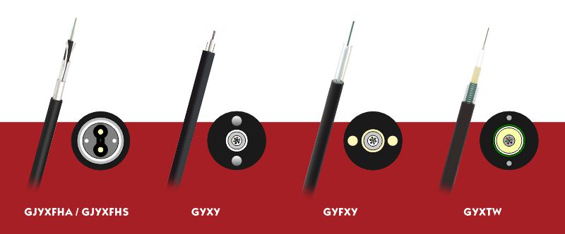
The current ZION duct fiber optic cable range includes central-tube and stranded constructions with metallic, non-armored, and all-dielectric options. The groups below describe construction logic; individual model codes may use different strength members, water-blocking systems, sheaths, and application ratings.
Central-Tube Armored Cables
A central-tube armored cable places the fibers in one loose tube and adds metallic protection, such as corrugated steel tape, around the optical core. A GYXTW PSP-armored central-tube cable is one example. This structure can provide a compact cable with additional crush and rodent resistance, but its steel elements introduce bonding, grounding, and induced-voltage considerations.
Stranded Loose-Tube Armored Cables
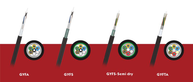
Stranded cables distribute fibers among multiple loose tubes around a central strength member. APL constructions use an aluminum-polyethylene laminated tape that primarily contributes a moisture barrier and limited mechanical protection. PSP or corrugated steel tape generally adds greater crush and rodent resistance, along with more weight and metallic-system requirements. A GYFS PSP-armored stranded loose-tube cable illustrates the steel-tape approach.
Stranded Loose-Tube Non-Armored Cables
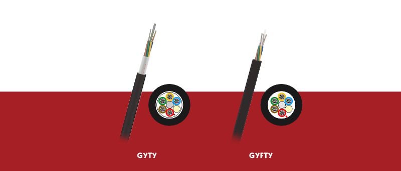
A non-armored cable omits an armor layer, but it is not necessarily metal-free. Some designs still use a steel central strength member or other metallic components. They are usually lighter and easier to handle than comparable armored constructions and can be suitable where the conduit provides sufficient protection and the route has a controlled rodent and crush risk.
All-Dielectric Stranded Loose-Tube Cables
All-dielectric cable excludes metallic armor and metallic strength members. Glass-fiber-reinforced plastic, composite strength members, aramid yarn, or glass yarn may provide strength and additional protection. This construction avoids electrical continuity and can simplify selection where induced voltage, grounding, or electromagnetic proximity is a concern. It does not make the cable immune to lightning, rodents, crushing, or moisture; those properties require the appropriate construction and test evidence.
Armored, Non-Armored, or All-Dielectric?
| Construction | Consider When | Main Trade-Off | Confirm |
| Steel-tape armored | Crush, impact, or rodent exposure justifies stronger protection | Higher mass, stiffness, and metallic-system requirements | Grounding, bonding, pulling load, and actual burial rating |
| APL or light metallic barrier | Moisture barrier and moderate mechanical protection are needed | Less robust than heavy steel armor for severe hazards | Tape function, overlap, sheath, and rodent test evidence |
| Non-armored | The duct route provides adequate protection and lower mass is useful | Lower resistance to severe crush or animal damage | Whether metallic strength members remain in the cable |
| All-dielectric | Electrical isolation or elimination of metallic bonding is important | Protection depends on non-metallic reinforcement and pathway design | Tensile, crush, rodent, fire, and environmental performance |
Candidate Model Families to Review
The following ZION model families provide a practical starting point after the construction type has been selected. Model codes are not a substitute for the final bill of materials or datasheet: confirm the strength member, armor, sheath, water-blocking system, fiber range, installation rating, and test values for the exact version being quoted.
| Project Need | Models to Review | Construction Direction | Verify Before Selection |
| Compact FTTH or short access duct | GJYXFHA, GJYXFHS, GYXY, GYFXY | Bow-type drop or compact central-tube cable | Indoor/outdoor rating, metallic parts, fiber count, pull length |
| Compact cable with steel-tape protection | GYXTW | Central tube with PSP or corrugated steel tape | Crush rating, grounding, cable diameter, burial approval |
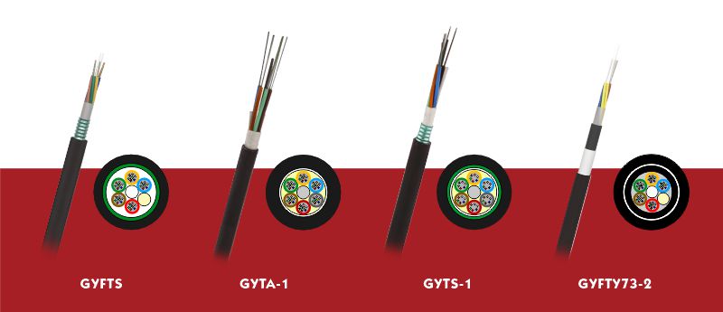
| Stranded cable with aluminum barrier | GYFA, GYFTA, GYTA-1 | Stranded loose tubes with APL moisture barrier | Strength member, APL function, pulling tension, application rating |
| Stranded cable with higher crush or rodent protection | GYFS, GYFTS, GYTS-1 | Stranded loose tubes with PSP or steel tape | Rodent evidence, armor bonding, bend limit, direct-burial rating |
| Reduced gel during cable preparation | GYFS Semi-dry, GYFY Semi-dry | Semi-dry water-blocking construction | Water-penetration test, armor content, sheath and route environment |
| Non-armored protected duct route | GYTY, GYFTY | Stranded loose-tube cable without metallic tape armor | Whether the strength member is metallic, crush risk, duct protection |
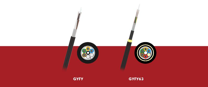
| Fully non-metallic route | GYFY, GYFTY, GYFY63 | GFRP, composite members, or glass-yarn reinforcement | Complete metal-free BOM, tensile rating, rodent and fire tests |
| Additional animal-damage deterrence | GYFY63, GYFTY73-2 | Glass yarn, FRP tape, or reinforced double-sheath option | Target animal, test method, installation rating, cable preparation |
Classification note: all-dielectric cables are also non-armored, so a model such as GYFTY may appear in both selection paths. The all-dielectric label is appropriate only when the complete quoted construction contains no metallic element.
Water Blocking and Sheath Selection
Ducts can contain water because of condensation, groundwater entry, damaged seals, or flooded chambers. Cable water blocking may use filling compound, water-swellable yarns and tapes, or a semi-dry combination. These systems are intended to limit longitudinal water movement; they do not make poor duct drainage or unsealed cable ends acceptable.
Gel-filled designs can provide established water-blocking performance but may require more cleaning during preparation. Dry or semi-dry designs can simplify access and splicing, while their water-penetration performance still depends on the complete construction. Select the outer sheath separately for the real environment: outdoor PE for weather and moisture durability, or an appropriately rated low-smoke material where indoor fire requirements apply.
Installation and Route Checks
Route condition: confirm duct continuity, internal diameter, occupancy, bends, chambers, water, debris, deformed sections, and draw-rope condition.
Installation load: calculate or control pulling tension, bend radius, sidewall pressure, capstan or winch settings, and lubricant compatibility.
Cable geometry: check outside diameter, mass, stiffness, minimum bend diameter, reel dimensions, and the available space at chambers and entries.
Metallic components: identify armor and strength members, then define bonding, grounding, separation, and induced-voltage measures where applicable.
Water management: seal cable ends, repair duct joints, manage drainage, and specify closure and entry seals for the actual flooding risk.
Acceptance: record drum and route identity, inspect the sheath, and complete the specified optical tests before and after installation.
Information Needed for a Duct Cable RFQ
Provide the supplier with enough information to select a complete construction rather than only a fiber count:
Application, route drawing, total length, pulling-section lengths, bends, elevations, chambers, and indoor transitions.
Duct material, inside diameter, occupancy, installation method, available pulling equipment, and maximum allowed cable diameter.
Fiber count and type, tube allocation, attenuation requirements, identification, splice plan, and spare capacity.
Armored, non-armored, or all-dielectric preference, plus rodent, crush, moisture, temperature, chemical, fire, and UV conditions.
Applicable standards, tensile and crush requirements, water-penetration test, drum length, packing, inspection, and delivery documentation.
Frequently Asked Questions
Should every underground duct cable be armored?
No. Armor is selected when the route needs additional crush, impact, or animal protection. A sound conduit route may allow a lighter non-armored cable. The decision should use the actual duct condition, installation load, environmental risk, and grounding requirements.
Does non-armored mean all-dielectric?
Not necessarily. A non-armored cable can still contain a steel central strength member or other metallic components. “All-dielectric” means the complete cable construction excludes metal.
Can a duct-rated cable be installed directly in soil?
Only when the selected product is explicitly rated and tested for direct burial. A generic duct rating does not prove that the cable can tolerate direct soil exposure and the associated mechanical and environmental hazards.
When should I choose central-tube instead of stranded loose-tube cable?
Central-tube designs are useful when compact size and a lower fiber count match the route. Stranded loose-tube designs are normally considered when the project needs more fibers, multiple tube groups, or a broader mechanical design range. Compare the actual datasheets before deciding.



 Fiber Optic Tools
Products 6 families
Solutions 6 markets
Resources Tools & docs
Certificate
Certification and compliance references for project review, qualification and purchasing documentation.
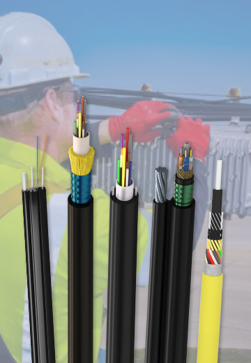 Fiber Optic CableAccess and backbone
 Ethernet CableCat5e to Cat8
 Coaxial CableRF and video signal
 Fire, Security & AlarmSafety systems
 Voice, Audio & VideoSignal cabling
 Power & Control CableEnergy and control
Fiber optic cable systems
Outdoor, indoor, FTTH and distribution cable lines for access networks, backbone routes and campus deployments.
 Telecom & ISP NetworksFTTH, PON, ODN
 Data Center InfrastructureServer room cabling
 Building Low-Voltage SystemsBMS, AV, weak current
 Security & Fire ProtectionAlarm, CCTV, access
 Industrial Automation CablePLC, RS485, fieldbus
 Energy & Power InfrastructureSolar, battery, power
Telecom & ISP Networks
For FTTH / PON access, outdoor fiber deployment, aerial routes, duct routes, direct burial routes, rural broadband and ODN planning.
Tools
Use calculators and planning tools for conduit capacity, PoE voltage drop and fiber optic link loss budget work.