
1. Confirm whether the short link needs fiber
If copper already satisfies data rate, environment, and power requirements, converting a short internal link to fiber may add media conversion, power points, and troubleshooting work.
Fiber is worth evaluating when equipment already has compatible optical ports, electrical isolation is required, the data route or installation conditions support fiber, or the interface has already been approved. Start from confirmed system requirements rather than replacing every copper link simply because the platform is an intelligent USV.
2. Establish the installed route before fixing length
Measure length along the secured route, not as a straight line between ports. Include connector boots, turns, fixing points, equipment withdrawal, and service slack.
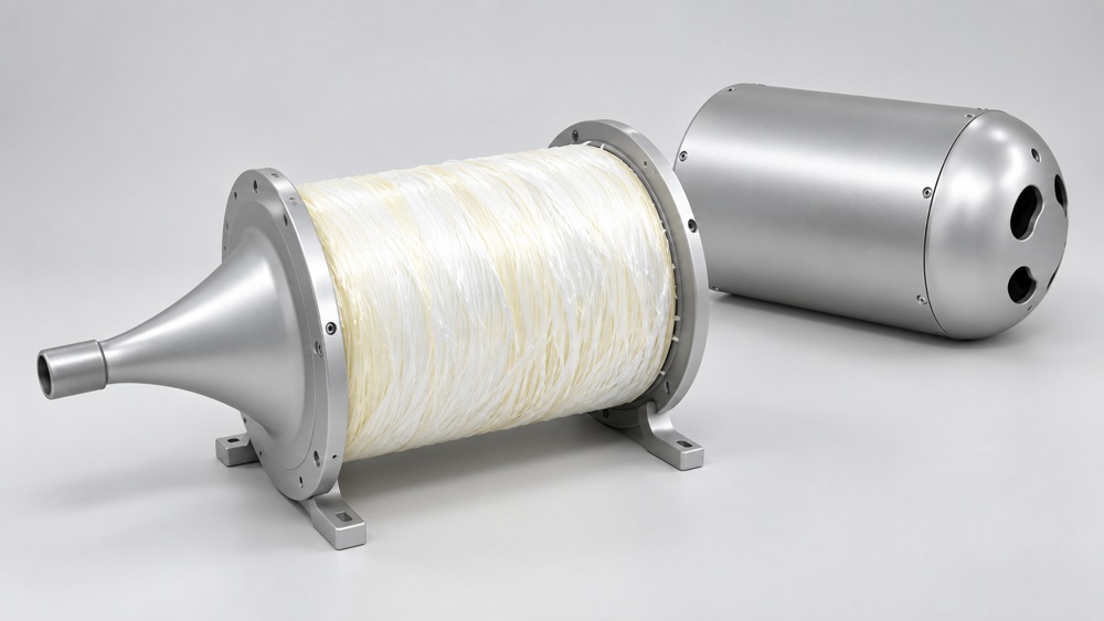
Too little slack transfers maintenance movement to the connector; too much consumes space and creates uncontrolled coils or hatch pressure. Establish the prototype route first, then define the measurement datum in the drawing—connector end face, boot end, or branch point.
3. Connector clearance may matter more than cable diameter
For a preterminated assembly, the connector, dust cap, or pulling protection often controls passage through an opening or conduit. Check both the narrowest section and every turn.
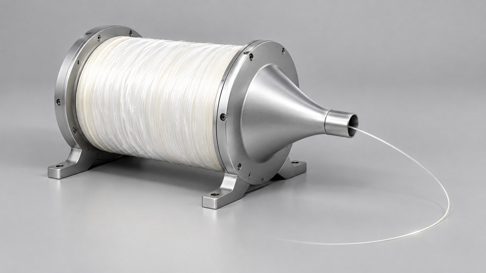
A connector that passes through a straight hole may not pass through a curved tube. Alternatives include changing the assembly sequence, adding a maintainable termination point, or using field splicing. The choice must support both production and service.
4. G.657.A2 is not permission for any bend radius
G.657.A2 can be considered where bend space is restricted. The current ITU-T G.657 (08/2024) covers bend-loss-insensitive single-mode fiber and cable characteristics and describes category A compatibility with G.652.D.
A finished assembly also contains jacket, strength members, branches, and connector boots. Its permitted installation and operating bend conditions cannot be replaced by one bare-fiber value. Repeatedly moving covers, removable masts, and similar positions also require separate bending, torsion, and mating-cycle review.
5. Make polarity, branches, and labels inspectable
Duplex links require the transmitter at one end to reach the correct receiver at the other. Multi-fiber assemblies must map every branch to a port table. “Duplex LC” alone is not a complete definition. ZION's fiber patch cord and pigtail specification generator can organize interfaces, fiber type, jacket, length, and test requirements before project-specific polarity and branch details are added.
| Item | Information to define |
|---|---|
| Optical interface | Single-mode or multimode, connector, polish, and matching port |
| Polarity | Transmit/receive mapping, fiber sequence, and port table |
| Geometry | Overall length, tolerance, branch lengths, and measurement datum |
| Mechanical build | Outside diameter, fixing locations, strain relief, and protection |
| Labels | Assembly ID, endpoint, direction, serial number, or batch |
| Inspection records | End-face inspection, optical testing, and dimensional checks |
Color can assist assembly, but labels and drawings must independently explain the connection. A service technician should identify the correct revision by assembly number rather than memory of the prototype.
6. Validate the sample after actual installation
Separate incoming inspection from installed-condition inspection. First verify interfaces, dimensions, labels, and agreed optical records. After installation, confirm route access, hatch closure, equipment serviceability, bend condition, and strain.
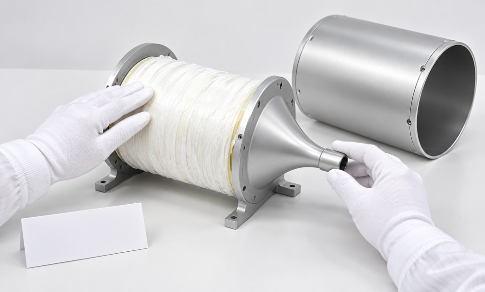
Where necessary, compare optical status before and after installation and complete interoperability validation in the customer's system. Light on the bench does not replace installed-condition acceptance. Freeze the validated drawing, BOM, and test requirements before volume production.
7. Move from one sample to repeatable supply
OEM supply depends on consistency: every batch must use the same length datum, identification method, and inspection rules. Procurement documents should control assembly revision, critical dimensions, labels, records, and packaging.
Review how changes to jacket, connector, branch structure, or length affect routing, securing, and service slack.
Protect connectors, control coil size, mark unpacking direction, and distinguish similar-looking spares by assembly ID.
8. Specify supporting components and application boundaries
ZION can discuss controlled-drawing builds for fixed-length preterminated assemblies, patch cords, branches, termination structures, and compact accessories such as fiber optic adapters. Order documents can define end-face inspection, optical test records, labels, and packaging.
Environmental suitability must be confirmed for the selected construction, prototype installation, and project requirements. IEC 60092-378:2024, including COR1:2025, applies to optical fiber cables intended for fixed shipboard and offshore installations. Its relevance to short jumpers, connectors, branches, or the complete vessel depends on the component use and the standard's scope.
9. Frequently asked questions
Does a smaller cable diameter always make an assembly better for a USV?
No. Mechanical protection, securing method, connector clearance, and actual assembly conditions must also be considered. An excessively small diameter can reduce handling or protection capability.
Can all service slack be coiled beside the connector?
Service slack should follow the finished assembly's bend limits and available maintenance space, without concentrating bends or continuous load at the connector boot.
Does every cable-length change require another fit check?
It depends on the impact. Repeat the fit check when a change affects fixing points, branch positions, service slack, or hatch clearance.
10. Prepare the OEM request for ZION
Provide endpoint and interface photos, assembly drawings, routed length, opening size, bend space, fixing points, quantity, labels, test records, and traceability requirements. If only a prototype exists, define the measurement method and open validation items before turning the build into a production specification.
A mature OEM fiber assembly is more than a custom-length patch cord: it gives procurement, assembly, testing, and service teams one controlled set of information.
References
- ITU-T G.657 (08/2024): Characteristics of bend-loss-insensitive single-mode optical fiber and cable
- IEC 60092-378:2024: Electrical installations in ships—Part 378: Optical fiber cables, including COR1:2025
Prepare an actionable compact-USV fiber assembly request
Send interface details, routed drawings, assembly length, connector clearance, quantity, labeling, and test requirements through the Sales Support page to begin sample and production review.
Request Project Support


