
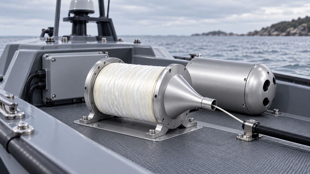
Cameras, radar, LiDAR, and monitoring instruments on a compact unmanned surface vessel may be distributed across the mast, bow, and stern, while computing and control equipment must fit inside a limited cabin. The communication design therefore has to account for traffic, available space, endpoint power, environmental exposure, and future maintenance.
The ZION compact fiber link package focuses on the passive optical connections required between these nodes. A prototype configuration can be built around 2- or 4-fiber cable, pre-terminated assemblies, patch cords, and optional termination hardware. After installation and system validation, the configuration can be frozen into a repeatable production BOM.
1. Suitable USV Platforms and Link Locations
The solution can be considered for unmanned patrol craft, surface-cleaning robots, water-quality monitoring boats, compact survey vessels, and other USV platforms with an optical communication requirement. Links that support rescue, alarm, maneuvering, or another critical function also require vessel-level safety, redundancy, failure-recovery, and regulatory assessment.
A short copper connection may remain appropriate when it already meets bandwidth, power, and environmental requirements. Fiber is particularly useful for evaluating the following locations:
| Link Location | Primary Task | Confirm Before Configuration |
|---|---|---|
| Mast to controller cabinet | Return sensor data to the computing area | Device interface, actual route, and mast removal method |
| Aggregated video uplink | Carry locally aggregated video to a compute node | Per-stream bitrate, concurrent load, protocol overhead, headroom, and uplink port |
| LiDAR and radar link | Carry point clouds, target information, or other output data | Output mode, protocol, sustained and peak traffic, latency, and synchronization |
| High-EMI area | Reduce susceptibility of the fiber segment to electromagnetic interference | Conversion points, endpoint power, and equipment environmental rating |
| Bow-to-stern connection | Create a cross-vessel data path | Isolation objective, conductive cable elements, and mechanical protection |
2. How Devices Connect to the Fiber Link
Typical path: camera or sensor → customer access or aggregation node → ZION fiber link → customer onboard network → control or computing equipment.
When a device includes an optical port, confirm the Ethernet variant, data rate, wavelength, fiber count, connector, transmit power, and receiver sensitivity. A device with only an RJ45 or another electrical interface requires a compatible switch or media converter. Serial and proprietary interfaces also require protocol-level confirmation; the connector shape alone is not a sufficient selection criterion.
Several devices can share one uplink, but the aggregation node becomes a common dependency whose failure impact must be covered by the system design.
Passive fiber does not deliver power. Cameras, radar, and conversion devices still need local power. PoE does not pass through a passive optical link.
3. Starting Configuration and Required Checks
The following options provide a starting point for technical discussion. Final selections depend on endpoint documentation, assembly drawings, applicable standards, and acceptance requirements.
| Item | Starting Option | Required Check |
|---|---|---|
| Fiber type | ITU-T G.657.A2 bend-insensitive single-mode fiber for compact routing | Verify the complete cable specification and optical interface compatibility |
| Cabling performance class | Specify OS2 when the project procures by structured-cabling class | OS2 and G.657.A2 describe different attributes; marine suitability requires separate verification |
| Fiber count | 2 or 4 fibers | Calculate from link count, transmit/receive method, and spare-fiber requirements |
| Link rate | Select from the traffic budget; 1 GbE is one option, not a default | Include sustained load, peak load, protocol overhead, headroom, latency, and port capability |
| Upgrade path | Evaluate future 10 GbE or another target rate during selection | Match ports, transceivers, wavelengths, fiber count, optical power budget, and network capacity |
| Connector | A duplex link commonly uses two LC/UPC connectors held in a duplex clip | Match the equipment interface, polish type, keying, and polarity; never mate UPC directly with APC |
| Cable construction | Small diameter, aramid reinforcement, and an LSZH jacket can be considered | Verify diameter, tensile load, crush, bend, temperature, and fire-related requirements |
| Termination method | Pre-terminated direct connection or compact termination-box arrangement | Select from pass-through diameter, service space, and installation method |
For ITU-T G.657.A2, 7.5 mm is one radius used to evaluate macrobending loss in uncabled fiber. It is not a blanket long-term bend limit for a finished cable, connector boot, or breakout. Use the most restrictive manufacturer limit across the cable, breakout tubing, boots, and installed condition.
Calculate the optical power budget from the actual transceivers and passive path. The difference between minimum transmitter output and receiver sensitivity must cover fiber attenuation, connectors, splices, other passive devices, measurement uncertainty, and engineering margin. In a short onboard link, connector and splice losses can matter more than the fiber length itself.
4. Should the Link Use 2 or 4 Fibers?
A conventional duplex bidirectional link uses two fibers to carry transmissions in opposite directions. It suits defined endpoints with no additional spare-fiber requirement.
One pair can carry the working link while the second pair remains available as same-route spares. Once the second pair is assigned to another service, it is no longer spare capacity.
Spare fibers in the same cable cannot protect against complete cable damage and do not switch traffic automatically. Automatic recovery or independent A/B paths require separate cable routes, endpoint equipment, power, and network mechanisms.
Single-fiber bidirectional, or BiDi, transceivers normally require matched transmit and receive wavelength pairs. Confirm the data rate, reach, connector, and optical power budget rather than applying a duplex-fiber design unchanged.
5. Two Termination Approaches
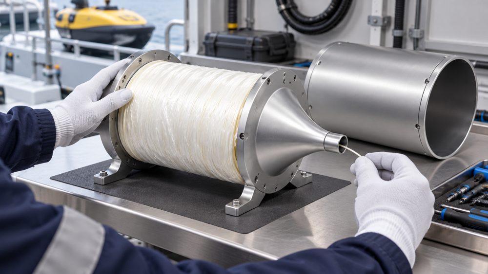
The termination method affects cabin space, installation work, service access, and BOM quantities. A project can choose between a pre-terminated direct assembly and a compact termination-box arrangement.
Option A: Pre-Terminated Direct Connection
When both endpoints have compatible optical ports, the route can pass the connector, and the assembly can be secured correctly, a fixed-length pre-terminated assembly can connect the two nodes directly. Before pulling, check that the connector, dust cap, and pulling protection can pass through all holes and bends. Pulling load must not be applied directly to a connector or breakout.
Option B: Compact Termination Boxes
Projects that need fixed termination, clear separation between trunk and equipment cords, or service access without handling the trunk directly can use a compact box at each end. The trunk can be fusion-spliced to pigtails or supplied with a pre-terminated structure compatible with the enclosure, followed by short equipment patch cords.
6. Example BOM
This example covers one point-to-point duplex link. Quantities change with the actual termination structure, installed endpoint equipment, and whether all spare fibers are terminated.
| Item | Pre-Terminated Direct Link | Fusion-Spliced Termination at Both Ends |
|---|---|---|
| Trunk or assembly | One 2- or 4-fiber pre-terminated cable assembly | One 2- or 4-fiber cable, length based on the route |
| Compact termination box | Optional, based on protection and maintenance needs | Normally two, one at each end |
| Single-fiber LC/UPC pigtail | Not required for direct connection | Four for a fully terminated 2-fiber cable; eight for 4 fibers |
| LC duplex adapter | Not required for direct connection | Two for a fully terminated 2-fiber cable; four for 4 fibers |
| LC/UPC duplex patch cord | Normally not added | Normally two for the working link, one at each end |
| Optical transceiver | One matched pair when required by the endpoint equipment | One matched pair when required by the endpoint equipment |
| Dust caps and cleaning supplies | As required for the interfaces and maintenance plan | As required for the interfaces and maintenance plan |
| Labels and fiber assignment sheet | Defined with the assembly | Cover the trunk, ports, working fibers, and spare fibers |
| Optical test record | Define wavelength, reference method, polarity, and insertion-loss record | Define separate test boundaries, methods, and limits for factory assemblies and the installed link |
7. Compact Installation and Marine Environment Checks
Measure length along the fixed route and define the reference points and tolerance. Too little service slack restricts maintenance, while excessive slack can create congestion and tight bends. After fixing the assembly, confirm that covers can close, equipment can be removed, and connectors are not carrying external tensile load.
- Electrical isolation: Check for metallic strength members, armor, and other conductive paths in the cable.
- Environmental exposure: Evaluate temperature, damp heat, salt mist or saltwater, oil, UV, vibration, shock, tensile load, and crush for the actual location.
- Fire behavior: LSZH describes only part of the material and combustion behavior. Confirm flame propagation, smoke density, acidity, and any required fire integrity.
- Water and corrosion protection: Exposed, wet, or washdown locations require verification of the complete assembly's ingress protection, sealing, material compatibility, and cable entries.
IEC 60092-378:2024, including COR1:2025, applies to optical fiber cables for fixed installation on ships and offshore units. Procurement documents should request construction, test, and approval evidence for the exact cable model. If classification-society approval is required, identify the society and document scope at the RFQ stage.
8. Testing and Delivery Records
Agreed inspection records for a pre-terminated assembly can include end-face condition, polarity, dimensions, and insertion loss. Visual end-face inspection can identify contamination, scratches, and defects, but it does not replace optical performance measurements.
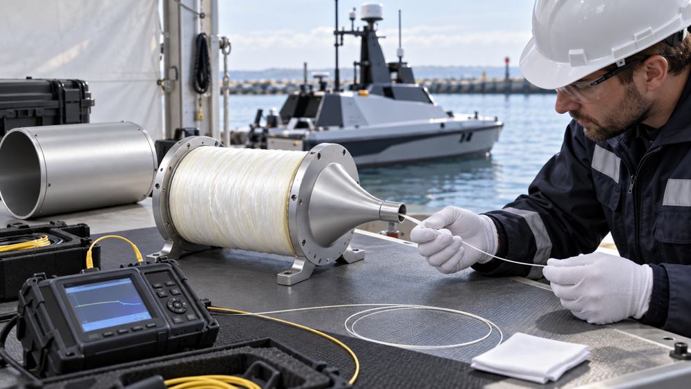
After installation, recheck continuity, polarity, and end-to-end loss. The acceptance record should identify the test boundary, wavelength, reference method, test-cord grade, pass/fail limit, and instrument. A light source and power meter or optical loss test set is suitable for validating total loss on a short onboard link. An OTDR is useful for locating events, but its suitability depends on link length, event spacing, and instrument dead zones.
Business-traffic validation for video, point-cloud data, synchronization, loading, and failure recovery belongs in the complete vessel system test. Maintain a traceable relationship among assembly ID, endpoint, length, fiber assignment, and test record for production installation and later replacement.
9. Frequently Asked Questions
Can a 1 GbE link be upgraded directly to 10 GbE later?
An upgrade is possible only when the fiber, cable, terminations, connector count, and optical power budget support the target application, and both endpoints have compatible 10 GbE ports, transceivers, wavelengths, and fiber arrangements. Replacing only the patch cords is not enough, and a 10G transceiver cannot be assumed to work in every 1G port.
Does a 4-fiber cable create a redundant network?
No. A 4-fiber cable can provide spare fibers within the same route, but independent routing, endpoint equipment, power, and network recovery mechanisms require separate design.
Does every small USV need two termination boxes?
Not necessarily. A pre-terminated direct link may not require termination boxes. A fusion-spliced arrangement normally uses a termination unit at each end, subject to pass-through diameter, service space, fixing, and installation conditions.
Can a radar or LiDAR without an optical port connect directly to the fiber link?
No. Confirm the device electrical interface, protocol, data rate, and conversion method first, then select a compatible switch or media converter and the corresponding fiber link.
10. Information Needed for Project Configuration
Prepare the vessel type and use case, installation zone, endpoint models and interfaces, sustained and peak traffic, latency or synchronization requirements, route length, connector pass-through diameter, environmental exposure, working and spare-fiber needs, quantity, applicable standards, and required test documents.
ZION can use this information to discuss 2- or 4-fiber cable, pre-terminated assemblies, termination hardware, and patching products, with the actual supply scope, part numbers, and open items identified in the quotation.
References
- ITU-T G.657 (08/2024): Characteristics of a bending-loss insensitive single-mode optical fibre and cable
- IEC 60092-378:2024, including COR1:2025: Electrical installations in ships — Part 378: Optical fiber cables
- IEC 61300-3-35:2022: Visual inspection of fibre optic connectors and fibre-stub transceivers
- IEC 61280-4-2:2024: Installed single-mode cabling attenuation and optical return loss measurements
Configure Your USV Fiber Link
Submit the endpoint interfaces, route length, installation environment, working and spare-fiber requirements, quantity, and test-document needs so ZION can prepare a project configuration and BOM.
Request Project Support


