Direct Buried Fiber Optic Cables | Anti-Rodent, All-Dielectric & Fire-Resistant Solutions
Author: Site Editor Publish Time: 07-04-2025 Origin: Site
Direct Buried Fiber Optic Cables: Construction and Selection Guide Compare armor, rodent resistance, metallic content, fire performance, and installation requirements before specifying an underground fiber optic cable.
A direct buried fiber optic cable is designed for underground placement without a continuous protective duct along the entire route. Its loose-tube core, water-blocking system, sheath layers, strength members, and optional armor work together to protect the fibers from moisture, crushing, pulling loads, soil movement, and biological damage. The correct construction depends on the route risk and the project specification; the phrase “direct buried” does not mean that every cable is suitable for every soil, electrical, fire, or rodent environment.
■What Makes a Fiber Cable Suitable for Direct Burial?
Direct burial suitability comes from the complete cable design, not from one jacket or armor layer. Common designs combine stranded loose tubes, longitudinal water blocking, an inner sheath, corrugated steel or other protective armor, and a durable outer sheath. The cable data sheet should state the permitted installation method and provide the tensile, crush, bend-radius, temperature, and water-ingress values for the exact fiber count and construction being ordered.
A direct buried cable can reduce duct material and installation work on suitable routes, but it does not remove the need for route engineering. Local requirements may still call for minimum cover, warning tape, separation from other utilities, protective conduit at crossings and entries, grounding or bonding of metallic components, and documented splice and test plans.
■Direct Buried Cable Construction Options
The following ZION models illustrate several construction choices. Product names are useful starting points, but the purchase specification and current data sheet should control the final selection.
GYTS53 — general steel-tape armored constructionA double-sheath design with PSP corrugated steel tape for mechanical and crush protection. It is a practical baseline when the route permits a metal-containing cable and the required tensile and crush ratings are confirmed.
GYFTA53-1 — PSP and aluminum-laminate protectionThis construction adds an aluminum polyethylene laminate moisture barrier to a PSP-armored, double-sheath design. It contains metallic layers and therefore requires the project team to address electrical continuity, bonding, and lightning exposure where applicable.
GYFTA54-1 — layered rodent-resistant constructionPSP armor, glass-yarn reinforcement, and a nylon outer layer provide multiple deterrent and protective mechanisms. Specify it as rodent-resistant rather than rodent-proof, and confirm the exact sheath sequence and environmental compatibility.
GYFY53 — FRP central strength member with PSP armorThe central strength member is fiber-reinforced plastic, but the listed PSP armor is steel tape. This model is therefore not fully all-dielectric. It may reduce metal in the strength-member system, yet it should not be specified as a non-conductive cable near power infrastructure.
GYFZS53 — fire-performance constructionThe product page lists flame-propagation, circuit-integrity, halogen-gas, and smoke-density standards. Before using the cable in a regulated tunnel, mine, subway, or building transition, request current test evidence for the exact ordered construction and confirm the required test method, duration, support arrangement, and acceptance criteria.

■How to Specify Rodent Resistance
Rodent resistance is a system of deterrence and mechanical protection, not an absolute guarantee. Corrugated steel tape creates a hard barrier, while glass yarn and nylon layers can make biting and penetration more difficult. Performance can still be affected by installation damage, exposed slack, poorly sealed closures, route conditions, and the local rodent population.
For higher-risk routes, document the expected pest exposure and specify the required protective layers instead of relying only on an “anti-rodent” label. Combine cable construction with good route housekeeping, sealed entries, protected handholes, and physical guarding where the cable is accessible.
■Metallic vs All-Dielectric Cable Near Electrical Infrastructure
An FRP central strength member does not by itself make a cable all-dielectric. If the construction also contains PSP steel tape, aluminum laminate, metallic moisture barriers, or metal strength members, the complete cable remains metal-containing. This distinction matters near substations, electrified railways, overhead power corridors, lightning-exposed routes, and locations where induced voltage or bonding requirements influence the design.
When a project requires a genuinely all-dielectric cable, the bill of materials should show non-metallic strength members and non-metallic armor throughout the construction. Confirm the complete cross-section and electrical requirements with the project engineer rather than selecting from the product name alone.
■How to Evaluate Fire Performance
“Flame-retardant” and “fire-resistant” do not describe the same test outcome. Flame-propagation tests evaluate how burning spreads under defined conditions. Circuit-integrity tests evaluate whether the cable continues to perform during a specified fire exposure. Smoke-density and halogen-gas tests address different hazards again. One result must not be used as proof of all the others.
For procurement, name the required standard and test part, exposure duration, performance criterion, and documentation. Also check the transition from an outdoor buried route into tunnels, buildings, or occupied spaces, because the permitted jacket and pathway can change at that boundary.
■Direct Buried Fiber Cable Selection Checklist
Define the route: soil condition, drainage, frost or settlement risk, road and rail crossings, utility congestion, and accessible sections.
Choose metallic or non-metallic construction: consider lightning exposure, induced voltage, grounding, bonding, and the owner’s electrical rules.
Set mechanical requirements: installation tension, crush load, minimum bend radius, pulling method, reel length, and expected service temperature.
Set environmental protection: water blocking, sheath material, chemical or hydrocarbon exposure, UV exposure at risers, and rodent risk.
Specify optical requirements: fiber type, fiber count, attenuation limits, link loss budget, splice plan, and spare capacity.
Verify special performance: exact fire tests, smoke and halogen requirements, third-party reports, and project-specific approvals.
■Installation and Acceptance Checks
Before installation, inspect the reel, verify the cable marking and ordered construction, and confirm the pulling plan against the manufacturer’s tension and bend-radius limits. Protect the cable at trench entries, crossings, sharp changes in direction, and locations subject to future excavation. Metallic elements should be handled according to the project’s grounding and bonding design.
Acceptance records should identify the installed reel lengths, splice locations, route changes, and test method. Optical loss testing should be planned for the link design and contract requirements; an OTDR trace and end-to-end loss measurement answer different questions and may both be required.
■Information to Include in an RFQ
A clear request for quotation should include:
Fiber standard, fiber count, route length, reel-length limits, and required spare length
Direct burial, ducted sections, crossings, risers, and indoor transition details
Metallic or fully non-metallic construction requirement
Armor, water blocking, sheath material, rodent exposure, and chemical environment
Required tensile, crush, bend-radius, and temperature values
Named fire, smoke, halogen, test-report, inspection, and delivery-document requirements
■Frequently Asked Questions
Can direct buried fiber optic cable be installed without conduit?
Yes, when the cable is rated for direct burial and the route design permits it. Conduit or other protection may still be required at road crossings, building entries, congested utility areas, or locations exposed to future excavation.
Is steel-tape armored fiber cable all-dielectric?
No. PSP is a plastic-coated steel tape, so a cable containing PSP armor is metal-containing even if it uses an FRP central strength member.
Is an anti-rodent cable completely rodent-proof?
No construction should be treated as an absolute guarantee. Steel tape, glass yarn, nylon, and route protection can improve resistance, but installation quality and local exposure remain important.
Does flame-retardant mean the cable will keep transmitting during a fire?
Not necessarily. Flame propagation, circuit integrity, smoke density, and halogen gas are separate performance areas with different test methods. Specify and verify each required result.
What should be confirmed before ordering?
Confirm the route, fiber type and count, metallic-content requirement, mechanical ratings, sheath and armor layers, reel length, installation temperature, special test standards, and the documentation required for acceptance.



 Fiber Optic Tools
Products 6 families
Solutions 6 markets
Resources Tools & docs
Certificate
Certification and compliance references for project review, qualification and purchasing documentation.
 Fiber Optic CableAccess and backbone
 Ethernet CableCat5e to Cat8
 Coaxial CableRF and video signal
 Fire, Security & AlarmSafety systems
 Voice, Audio & VideoSignal cabling
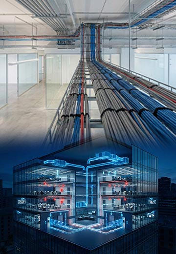 Power & Control CableEnergy and control
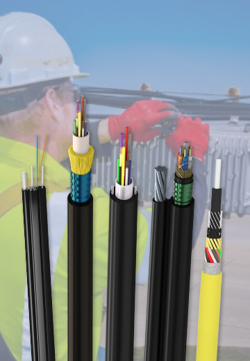
Fiber optic cable systems
Outdoor, indoor, FTTH and distribution cable lines for access networks, backbone routes and campus deployments.
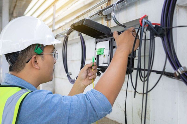 Telecom & ISP NetworksFTTH, PON, ODN
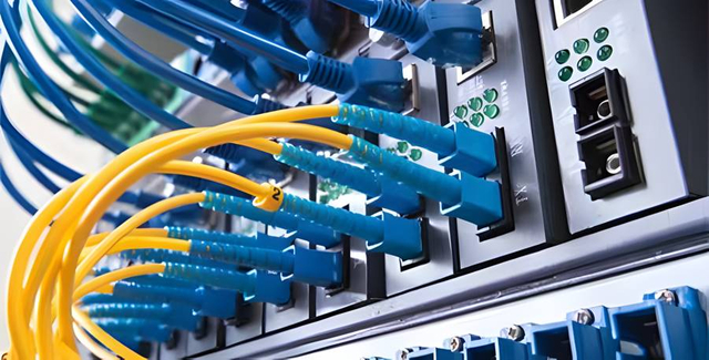 Data Center InfrastructureServer room cabling
 Building Low-Voltage SystemsBMS, AV, weak current
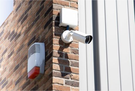 Security & Fire ProtectionAlarm, CCTV, access
 Industrial Automation CablePLC, RS485, fieldbus
 Energy & Power InfrastructureSolar, battery, power
Telecom & ISP Networks
For FTTH / PON access, outdoor fiber deployment, aerial routes, duct routes, direct burial routes, rural broadband and ODN planning.
Tools
Use calculators and planning tools for conduit capacity, PoE voltage drop and fiber optic link loss budget work.