
1. Separate Four Meanings of “Spare”
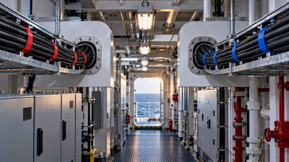
Spare fibers, two cables, separated routes, and a complete dual network address different failure levels. The appropriate arrangement depends on business impact, allowable interruption, and the required recovery method.
| Configuration | What it provides | What it does not automatically solve |
|---|---|---|
| Spare fibers in one cable | Replacement resources for fiber or port maintenance | Loss of the complete cable |
| Two cables on the same route | Separate administration or added link capacity | One impact, work activity, or fire affecting both |
| Two cables on separated routes | Lower exposure to a single route event | Shared equipment or shared power failure |
| Complete dual-network design | A defined response to specified failures | Failures outside the design and validation scope |
2. Mark Common Failure Points on the Drawing
Review each backbone from port to port. A shared bulkhead entry, narrow passage, unsegregated terminal box, common switch, or single power source can make nominal Route A and Route B fail in the same event.
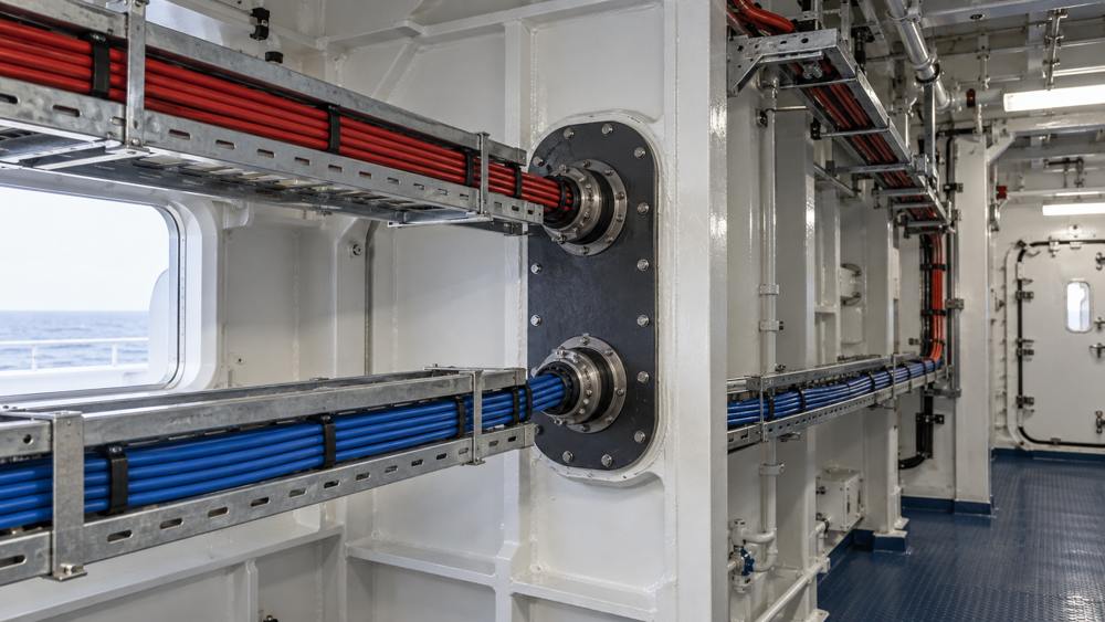
If the routes are separated for most of their length but run together through a mechanically exposed final section, that section remains a common failure point. The response may require rerouting, added protection, or an architectural change—not simply a higher fiber count.
3. Physical Redundancy and Network Switching Are Different
Fiber cables provide optical transmission paths. Automatic service recovery depends on endpoint equipment, network protocols, configuration, power, and application behavior. A standby path and two simultaneously active networks impose different requirements on ports, traffic management, and fault response.
IEC 61162-460:2024 supplements IEC 61162-450 for specific Ethernet environments used by shipboard navigation and radiocommunication equipment, including provisions concerning equipment, networks, interconnection, and redundant networks. It is not a universal redundancy standard for every shipboard business network, and citing it does not make one cable or distribution box a system-level solution.
4. Derive Fiber Count from Links, Not Ship Length
A longer vessel may require longer cables, but not necessarily more fibers. Core count is driven mainly by the number of physical links, transmission method, maintenance spares, and planned expansion.
Illustrative example: If one Route A segment carries three independent duplex links, it needs six working fibers. Reserving one additional duplex link for maintenance brings the example total to eight fibers. The selected cable count must still match available constructions, termination capacity, and expansion plans. Route B should be calculated from its own link schedule.
Confirm endpoints, transmission method, and port count for every service link.
State whether spares support repairs, future nodes, or another planned use.
Coordinate fiber count with termination capacity, installation space, and procurement options.
Single-fiber bidirectional optics, alternative topologies, or other optical interfaces require a fresh calculation. A fixed spare percentage is also insufficient without a defined maintenance and growth plan.
5. Preserve Route Identity Through Distribution
Distribution management must let maintainers determine which route a port belongs to, where it terminates, which service it carries, and whether its test record matches the latest as-built revision.

- Cable identifier and actual route;
- A/B network identity;
- Origin, destination, and intermediate termination points;
- Fiber and port numbers;
- Working, spare, and reserved uses;
- Test records and the latest as-built revision.
Color can support identification, but it should not be the only method. Labels must remain understandable in low light and after patch-cord changes. Separate enclosures or other segregation measures should follow the approved project design.
6. Include Installation Environment and Bulkhead Conditions
One backbone may cross dry equipment spaces, areas near machinery, and other environments. Cable construction and installation methods should cover the most demanding applicable conditions along the complete route.
Fixed shipboard fiber cables may be evaluated against the project-applicable edition of IEC 60092-378:2024, including COR1:2025. Cable selection and installation conditions may also need to consider IEC 60092-352:2025 and other project requirements. The responsible party confirms the final standard editions, classification rules, and approval documents.
Fire resistance, flame retardance, oil resistance, mechanical protection, and water protection are different properties. A broad “marine LSZH” description cannot replace the complete requirement, and route separation must not compromise an approved bulkhead penetration system.
7. Test Both the Fiber Paths and the Failure Scenarios
Each path should be checked independently for end-face condition, polarity, insertion loss, and consistency with the port schedule, with records retained as required. OTDR can help characterize and locate the path, but it does not prove complete network redundancy.

The integration and commissioning team should execute failure verification under an approved plan: what happens when a route becomes unavailable, whether standby equipment takes over as designed, and whether alarms operate correctly. Live critical systems should not be disconnected or powered down without approval. A requirement stated as “no interruption” also needs an affected service, test condition, and acceptable behavior.
8. Information Needed to Prepare the Fiber BOM
ZION can discuss dual-route cables, pre-terminated assemblies, ODFs, terminal boxes, patch cords, pigtails, adapters, and identification based on customer-confirmed routes and fiber assignments. Prepare the following information so the passive package aligns with the system design:
- Approved or review-stage topology and A/B physical route drawings;
- Origins, destinations, lengths, link counts, and transmission methods for each route;
- Definitions for working fibers, maintenance spares, and future expansion;
- Termination locations, connectors, distribution capacity, and labeling rules;
- Environmental, penetration, protection, and applicable-standard requirements;
- Required factory documents, port schedules, test records, and site acceptance responsibilities.
Switch redundancy protocols, dual-homed equipment, power arrangements, and functional system validation should be coordinated within the corresponding design and integration scope and tied clearly to the same topology, BOM, and test plan.
9. Frequently Asked Questions
Can spare fibers in one cable replace a second cable?
No. Spare fibers share the same cable-level mechanical risks as the working fibers, although they can support maintenance, port replacement, or expansion.
Must Route A and Route B have the same fiber count?
Not necessarily. Calculate each route from the confirmed topology and link schedule. Counts may match when both routes carry equivalent independent links, but this should not be assumed.
Can cables be purchased before the redundancy method is finalized?
This is not recommended. Routes, endpoints, recovery targets, interfaces, and installation environments affect fiber counts, ports, and distribution hardware.
Conclusion
The central task in a dual-route shipboard fiber backbone is to define what each route carries, which failures can still affect both routes, and how the system detects and recovers from those failures. Converting those decisions into route drawings, link schedules, a fiber BOM, an identification plan, and acceptance tests provides more engineering value than simply adding a second cable.
References
Align the Dual-Route Fiber BOM with the System Design
Use the Sales Support page to submit the A/B route drawing, link schedule, lengths, connectors, installation environment, applicable standards, quantities, and test-document requirements.
Request Project Support


