
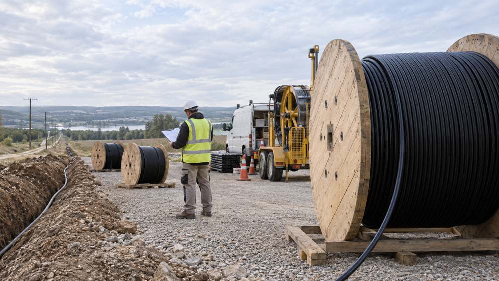
Ordering fiber optic cable by total route length is only the first step. Joint locations, service slack, cable construction, installation stages, access conditions, drum handling, and usable remnants all affect the result.
Separate Drum Length from Installation Distance
Three related lengths must be defined before a project team compares supply plans.
| Term | Meaning | Planning implication |
|---|---|---|
| Supply drum length | The continuous cable length delivered on one drum | Subject to product, manufacturing, packaging, transport, and handling limits |
| Continuous cable section | The cable between planned cable-end joints or terminations | May pass through several chambers and be installed in several stages without being cut |
| Pulling or blowing stage | The distance covered in one installation operation | Depends on route geometry, cable limits, duct condition, equipment, and crew procedure |
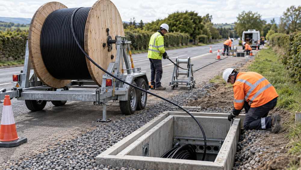
A long drum does not imply one pull or blow of the same length. Approved center-pull, backfeeding, or intermediate-assist methods can place a continuous cable in several stages without cutting it. Corning describes these methods in its duct installation procedure. An access chamber or equipment repositioning point therefore does not automatically require a splice.
Are 2 km, 4 km, 6 km, 8 km, and 12 km Drums Practical?
These lengths are useful comparison options, not a universal set of industry-standard sizes or guaranteed choices for every cable design.
| Candidate length | When it may be worth evaluating | Main checks |
|---|---|---|
| 2 km | Short sections, distributed deliveries, or restricted handling access | Whether additional cable-end joints outweigh the handling benefit |
| 4 km | Sections that fit inside the usable supplied length after allowances | Whether end preparation and planned slack have been included |
| 6 km | Longer continuous sections with an approved staged installation plan | Drum dimensions, gross weight, staging, and access |
| 8 km | Routes where fewer cable-end joints provide measurable value | Product availability and intermediate installation operations |
| 12 km | Selected products and routes supporting a long continuous section | Manufacturing confirmation, transport, staging, and remnant use |
Long supply lengths are technically possible for selected cable designs. For example, Prysmian lists maximum reel lengths of 18,400 m for selected Sirocco variants and separately describes demonstrated cascaded blowing distances. Those figures represent a specific product family and different specifications; they do not establish a universal single-stage installation distance. See Prysmian's Sirocco product data.
For the same construction, a longer supplied length increases cable mass. Across different constructions, however, a short drum of heavy armored cable may be harder to handle than a longer drum of compact microcable. Compare actual drum dimensions and gross weights rather than length alone.
Calculate Cable Requirements by Section
Calculate each planned continuous cable section from a defined measurement basis. This prevents missing length and double-counting allowances.
A map distance may omit vertical transitions and routing inside chambers. An aerial route needs an allowance for its designed cable path, including sag. Do not add these items again if the survey measurement already contains them.
Routed length plus intentional service or maintenance slack.
Lengths used in preparation or removed under the approved method.
Planned restoration stock and remaining cable available for reuse.
A balance without an identified application or justified recoverable value.
A percentage allowance can support early budgeting, but it should not replace a section schedule once survey data is available. For example, a 3,860 m horizontal path plus 40 m of vertical transitions, 60 m of end access and preparation, 40 m of service loops, and 20 m of approved contingency requires 4,020 m. These figures demonstrate the method; they are not standard allowances. A nominal 4,000 m drum would be too short.
Worked Example: What a 25.1 km Route Does—and Does Not—Tell You
Assume a 25.1 km surveyed route and a hypothetical 2% aggregate allowance for an initial purchasing comparison.
The 2% is an example assumption, not an industry recommendation. In this comparison it represents the entire provisional allowance above route distance; no separate slack percentage is added.
| Supply plan | Total supplied | Balance above 25.602 km | Idealized intermediate joints |
|---|---|---|---|
| 13 × 2 km | 26 km | 0.398 km | 12 |
| 7 × 4 km | 28 km | 2.398 km | 6 |
| 5 × 6 km | 30 km | 4.398 km | 4 |
| 4 × 8 km | 32 km | 6.398 km | 3 |
| 3 × 12 km | 36 km | 10.398 km | 2 |
| 12 + 8 + 4 + 2 km | 26 km | 0.398 km | 3 |
| 8 + 8 + 8 + 2 km | 26 km | 0.398 km | 3 |
The mixed plans show how total supplied length and piece count can be considered together. The second mixed plan produces the same arithmetic without a 12 km drum, although its joint positions differ.
These are purchasing scenarios, not approved installation schedules. The balance is not automatically waste, and the table does not prove that shorter drums always minimize surplus or that longer drums always minimize total cost. Individual pieces can still be too short for required route sections even when the total supplied length is sufficient.
Count Joints, Fiber Splices, and Installation Setups Separately
For one simple unbranched route assembled from N continuous cable pieces, the idealized number of intermediate cable-end joints is N − 1, excluding end terminations.
Purchased drum count is only a proxy when each drum contributes exactly one installed piece. A drum cut for several routes, mandatory equipment interfaces, or a branched network requires another count. A mid-span access closure can also leave through fibers uncut.
Joint locations and individual fiber splices are different quantities. If all 144 fibers are joined at each of three straight-through joints, the work includes 432 individual fiber splices. It does not necessarily mean 432 splicer cycles when compatible ribbon mass-fusion methods are used. Estimate labor from fiber count, splice method, cable preparation, tray organization, closure assembly, access, and required testing.
Fewer joints may reduce splice preparation and event-verification work, while required end-to-end acceptance tests remain. OTDR evaluation and insertion-loss testing serve different purposes. The test schedule should follow the contract and applicable procedures; the FOA Installation Standard 2025 distinguishes their roles.
Check Installation and Delivery Feasibility
Supplier confirmation of a manufacturable length must be matched by the contractor's installation plan and the designer's approved route and joint layout.
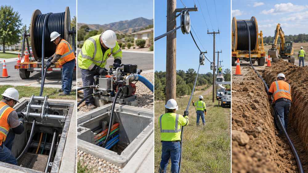
- Duct pulling: check pulling tension, loaded bend radius, bends and sidewall loading where applicable, route friction, access, and assist locations.
- Cable blowing: check cable-to-duct compatibility, duct condition and airtightness, bends, elevation, push-force limits, air supply, and staged installation arrangements.
- ADSS: use the approved span and sag-tension design, compatible hardware and sheaves, and cable-specific stringing limits. A mechanical tensioning boundary is not automatically a fiber splice location. AFL's ADSS installation guide emphasizes cable-specific sag and tension planning.
- Direct burial: confirm the approved cable construction, placement method, crossings, work sequence, and drum access.
Also check drum barrel and flange dimensions, winding width, cable mass, total shipping weight, transport clearances, unloading equipment, reel stands, and trailer ratings.
Compare Costs Without Counting Surplus Twice
Use mutually exclusive cost categories so that one expense is not charged twice.
If the cable purchase price already covers the entire supplied quantity, the purchase cost of unusable remnants is already included. Do not add that same material value again as a separate waste cost.
Only apply residual-value credit when an identified reuse or realistic recoverable value exists. Otherwise, use zero credit. Custom lengths may reduce unallocated cable but can involve different prices, minimum quantities, or lead times. Extra civil work belongs in the comparison only when the chosen plan actually requires it; an additional closure does not always require a new chamber.
Do not convert a reduction in joint count directly into a percentage labor saving. If lifecycle cost is evaluated, state the analysis period and maintenance assumptions separately from initial installed cost.
Turn the Selected Plan into an RFQ and Drum Schedule
Give the supplier the cable specification, section requirements, installation methods, delivery sequence, and site handling limits. The schedule should be detailed enough to connect procurement, manufacturing, logistics, and field installation.
| Schedule field | What to record |
|---|---|
| Section and cable identity | Route endpoints, cable SKU, fiber type, count, and construction |
| Length requirement | Minimum usable continuous length, measurement basis, allowances, and agreed tolerance |
| Production and delivery | Proposed order length, drum ID, delivery sequence, dimensions, and gross weight |
| Site installation | Feed positions, installation stages, approved direction, and handling requirements |
| Joint plan | Cable-end joints, branch access, and end terminations identified separately |
| Quality and traceability | Factory tests, drum-linked records, and cable length markings |
| Remaining cable | Intended reuse, restoration-stock allocation, storage, or disposal route |
At quotation stage, ask for proposed nominal lengths and tolerances. Before shipment, confirm actual manufactured lengths, weights, drum IDs, and associated test records. Keep ADSS, duct, and direct-burial cable allocations separate unless the project specification explicitly confirms the same construction for those applications.
Treat Remaining Cable as Managed Inventory
A remnant can be useful when its length and construction match an identified need and its condition remains verifiable. Record its length, original drum or batch identity, related test records, storage location, and intended use. Protect and seal cable ends according to the manufacturer's instructions.
There is no universal minimum reusable remnant length. A 300 m piece may be valuable for one network and unsuitable for another. Restoration stock should be planned against repair needs rather than justified only because cable remains after installation.
Fiber Cable Drum Length FAQ
Is the longest fiber cable drum always the most economical?
No. A longer drum may reduce cable-end joints, but the result also depends on section lengths, usable remnants, drum handling, transportation, installation staging, equipment, and site access.
Does a 12 km cable drum require one 12 km pull or blow?
No. Supply drum length, continuous cable section length, and individual pulling or blowing stage are different quantities. Approved center-pull, backfeeding, cascade, or intermediate-assist methods may install one continuous cable in multiple stages.
How many intermediate joints are created by N cable pieces?
For one simple unbranched route assembled from N continuous cable pieces, the idealized number of intermediate cable-end joints is N minus 1, excluding end terminations. Branches, mid-span access, equipment interfaces, and multiple routes require a project-specific count.
What should an RFQ include for drum-length planning?
Include the exact cable specification, required continuous length for each section, the measurement and allowance basis, permitted joint locations, installation method, drum size and weight limits, delivery sequence, tolerances, factory test requirements, and the intended use of remaining cable.
Prepare a Project-Specific Drum Schedule
Submit the cable specification, section-length schedule, installation method, drum size and weight limits, destination, delivery sequence, and required test documentation. ZION can confirm available continuous lengths and provide the production and packing information needed for quotation review.
Request Project Support


