
For operators, ISPs, utilities and campus or industrial network owners, readiness involves more than a fusion splicer and a spare cable drum. Crews need verified fiber records, accessible work locations, compatible materials and an agreed testing procedure.
Preparation can reduce avoidable delays. Actual restoration time still depends on the extent of damage, site conditions, available crews and the network's protection arrangements. This guide focuses on terrestrial cable-plant repairs, particularly outside-plant routes and campus connections.
1. Define What Must Be Restored First
Service recovery and physical cable repair are separate milestones. Traffic may be restored over an alternate path while the damaged cable remains out of service. Conversely, completing the splices does not establish that every affected service is operating correctly.
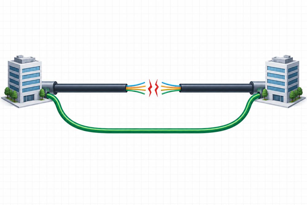
For each critical route, record the affected services, their restoration priority and any approved protection or rerouting options. Confirm that an alternate path has sufficient capacity and does not share the same vulnerable duct, bridge or pole line.
Unused fibers can help when individual fibers or terminations fail and an intact end-to-end path remains available. They cannot bypass a complete cut through the same cable. The FOA restoration guide discusses spare fibers, service loops, documentation and advance preparation as parts of restoration readiness.
Include the following in the route record:
- Cable and fiber identifiers, construction and allocation.
- Closure, handhole, manhole and pole locations.
- Accessible slack and approved working locations.
- Site-access restrictions and contractor coverage.
- Approved substitute materials and their limitations.
Set separate targets for mobilization, priority-service recovery and permanent repair. Define when each clock starts and who confirms completion.
2. Qualify Spare Cable Before an Outage
When sourcing fiber optic cable, a matching fiber count is only one part of cable compatibility. Review optical performance, installation requirements and the interfaces with closures and hardware.
Optical and splicing compatibility
Record the installed fiber specification, operating wavelengths and applicable link-loss budget. For multimode routes, also verify core size, fiber category and the requirements of the installed application.
For single-mode networks, G.657.A1 and G.657.A2 fibers comply with G.652.D requirements under ITU-T G.657 (08/2024). A different designation does not automatically make a replacement incompatible. However, the complete cable must still meet the route specification, and the repaired link must meet its acceptance criteria. Do not assume that every single-mode fiber category is interchangeable.
Before approving a substitute, check the splicing process and fiber-management requirements. Coating diameter, ribbon format, fiber pitch and the required holders or preparation tools can affect field work. Document any change in tube or fiber identification rather than relying on color alone.
Installation and mechanical compatibility
Use the cable manufacturer's limits for pulling tension, installation and operating bend radii, temperature and crush performance. A bend-radius specification for an individual fiber is not an installation limit for the finished cable.
| Route type | Replacement checks |
|---|---|
| ADSS aerial span | Span and loading conditions, sag and tension, compatible suspension and dead-end hardware, and electrical-environment requirements where applicable |
| Duct route | Cable and duct dimensions, pulling limits, water exposure and installation method |
| Microduct route | Cable–microduct combination, blowing equipment and installation limits |
| Direct-buried route | Explicit suitability for burial, water blocking, mechanical protection and any required locating provisions |
| Building or indoor/outdoor route | Environmental suitability and the fire-performance classification required for the installation |
ADSS selection requires more than matching diameter. For example, AFL's ADSS guidance links cable selection to span conditions, hardware and sag–tension calculations.
Direct burial does not universally require metallic armor. Select a construction qualified for the site; apply bonding and grounding requirements when conductive components are present. Manufacturer portfolios include different burial-rated constructions, as illustrated by CommScope's fiber cable ordering guide.
Keep low-smoke zero-halogen (LSZH), flame-spread performance and fire resistance distinct. LSZH alone does not establish that a cable will maintain optical continuity during a fire. Specify the required classification and supporting test evidence. The IEC treats combustion-gas characteristics and smoke measurement as separate test subjects.
Length and stock quantity
Estimate replacement length from the actual repair path, including diversions, slack, cable preparation and access to suitable jointing locations. A short damaged section may require a substantially longer replacement if the nearest usable work locations are far apart.
A cut-out repair commonly introduces two joints, but this is not a universal rule. Recoverable slack or replacement between existing closures may allow a different arrangement. Each joint must accommodate the fibers scheduled for reconnection, and the resulting loss must remain within the approved budget.
Set stock quantities using credible damage scenarios, simultaneous incidents, replenishment lead times and transport constraints. There is no universal spare-cable length or stocking percentage suitable for every network.
3. Stock Complete Closure Configurations
Choose a splice closure by its usable configuration, not only its advertised maximum fiber capacity.
Confirm cable-entry dimensions and shapes, supported sealing kits, tray type, splice-protector compatibility and space for uncut fibers or buffer tubes. Single-fiber, conventional ribbon and rollable-ribbon configurations may have different capacities. CommScope's FOSC 450 ordering guide illustrates how tray configuration and slack-storage requirements affect capacity.
Verify suitability for the intended installation and exposure conditions. Follow the selected model's assembly, re-entry and seal-verification instructions; do not assume every sealing component is reusable.
A route-specific closure package may include:
- The closure body and correct number and type of trays.
- Cable-entry seals, plugs and any required branch-off components.
- Cable fixation and strength-member clamps.
- Fiber-routing components and compatible splice protectors.
- Mounting hardware and identification labels.
- Bonding accessories where required by the cable and installation design.
Separate heat-shrink cable-entry seals from fusion-splice protection sleeves in the bill of materials (BOM). They serve different purposes and are not interchangeable.
Where practical, trial-fit a representative cable with the selected entry kit before approving the package. This can reveal missing components or unsuitable dimensions before an outage.
4. Prepare Tools for the Actual Network
Organize fiber optic tools and restoration resources around the tasks crews will perform.
| Resource group | Typical contents and readiness checks |
|---|---|
| Cable preparation | Sheath, armor and tube tools appropriate to the cable; fiber strippers; cleaning supplies; safe fiber-offcut container |
| Splicing | Fusion splicer, cleaver, correct holders, approved splice protectors, spare electrodes and charged batteries |
| Testing | Suitable OTDR, launch and receive fibers, optical loss test equipment, reference cords, connector inspection and cleaning tools |
| Installation | Compatible grips or blowing equipment, cable handling equipment, clamps, brackets and closure kits |
| Site support | Lighting, power, weather protection, communications and resources required by the approved site-safety plan |
For live PON troubleshooting, specify instruments and methods compatible with the deployed network, including filtering and maintenance-wavelength requirements. An ordinary OTDR or broadband power meter is not automatically suitable for every live PON measurement. EXFO's PON testing guidance distinguishes dark-fiber construction testing from live-network troubleshooting.
Follow optical-safety procedures and do not look into a fiber or connector. Identify live circuits before disconnecting or testing them. Excavation, confined-space entry and work near power infrastructure require the appropriate personnel and site procedures; a tool inventory does not replace these arrangements.
5. Keep Stored Materials Ready for Deployment
Assign an owner to the restoration inventory. Record part numbers, approved substitutions, quantities, storage locations and replenishment responsibilities.
Inspect cable drums for damage, maintain cable-end seals and follow the manufacturer's storage instructions. Identify and record usable lengths on partly consumed drums. Track the storage conditions and usable life of seals, adhesives and other consumables where specified.
Maintain equipment, batteries and calibration or verification records as applicable. Schedule readiness checks based on usage and storage conditions, and replenish kits after every deployment. Keep essential route records available offline with controlled access and a visible revision date.
6. Plan Temporary Recovery and Permanent Repair Together
Temporary recovery may involve an approved traffic diversion, an intact spare fiber path, a protected bypass cable or reconnection of priority fibers first.
Check the optical budget before adding cable length, splices or connectors. Temporary cables still require suitable support, bend control and protection from vehicles, weather and accidental movement.
Priority splicing must also be practical for the cable construction. With ribbon cables, the splicing method and fiber grouping can affect how individual services are restored. Continuing work inside a closure must be planned to avoid disturbing fibers already returned to service.
For every temporary arrangement, record:
- The services and fibers restored.
- The route and materials used.
- Remaining restrictions or incomplete work.
- The responsible owner and permanent-repair deadline.
- Any further service interruption required for the final changeover.
Permanent repair should address the damaged infrastructure and any loss of route resilience, as well as the cable itself.
7. Agree Contractor and Dispatch Responsibilities
An emergency contact list is useful only if the parties have agreed what support is available.
Confirm coverage area, operating hours, mobilization targets, escalation contacts, equipment and cable-handling capability. Specify responsibilities for materials, site access, civil work, traffic management, testing and reporting.
Check the contractor's experience with the installed cable types, especially high-count or ribbon designs. Define how response commitments apply during a regional incident when several customers may need the same crews.
Separate arrival or mobilization commitments from service-restoration targets. Neither a stocked warehouse nor an available splicer can remove an access restriction or resolve extensive infrastructure damage on its own.
8. Define Acceptance Before the Repair Starts
The test plan should state the fibers to be tested, test wavelengths, reference method, limits, required records and authorization to return services to operation.
Use the appropriate tests for different questions:
- Fiber identity and continuity: Has the intended path been reconnected?
- Insertion loss: Does the repaired path meet its specified loss budget? Use the agreed optical loss test set or source-and-power-meter method where required by the acceptance plan.
- OTDR analysis: Where are events, and are new splices or bends acceptable?
- Reflectance or optical return loss: Does the link meet these requirements where specified?
- Service verification: Are the affected services operating within their agreed criteria?
OTDR event analysis does not replace a required insertion-loss test. The FOA installation guidance distinguishes cable-loss acceptance from OTDR investigation of individual events.
For single-mode splice-loss acceptance, use bidirectional OTDR results at the same wavelength and average the corresponding event losses. Differences in backscatter can make a splice appear to gain power in one direction or exaggerate its loss in the other. Also account for dead zones and event resolution. See the FOA explanation of OTDR measurement uncertainty.
OTDR distance is a measurement along the fiber, not an exact excavation coordinate. Correlate it with route records, slack and known landmarks. Baseline comparisons should use compatible settings.
If emergency access permits only limited testing, record the limitation and schedule the outstanding acceptance work. Keep the service-restoration decision separate from final repair closeout.
9. Build a Route-Specific Restoration BOM
A useful BOM connects each item to an approved repair scenario.
| Route family | Core package | Configuration details to confirm |
|---|---|---|
| ADSS | Qualified cable, compatible suspension and dead-end hardware, closure and slack storage | Span/loading conditions, mounting and electrical environment where relevant |
| Underground duct | Qualified cable, installation accessories, closure and entry seals | Duct access, pulling limits and working space |
| Direct buried | Burial-rated cable, qualified closure and mechanical protection | Excavation, locating provisions and bonding where applicable |
| FTTH distribution | Appropriate distribution or drop cable, closure or terminal, compatible connection components | Fiber allocation, connector interface, optical budget and PON test method |
Include splitters only where the repair scope requires them, with the specified split ratio and optical characteristics. Do not treat every distribution repair as a splitter replacement.
For each item, record quantity, part number, approved substitute, compatible route, storage location and replenishment lead time. Review the BOM after repairs and whenever the installed design changes.
Fiber Restoration Readiness Checklist
- ☐ Critical services and restoration priorities are documented.
- ☐ Alternate paths have verified capacity and understood shared risks.
- ☐ Spare cable meets the optical, mechanical and installation requirements.
- ☐ Stock lengths support the planned repair scenarios.
- ☐ Closures include the correct trays, entry kits and accessories.
- ☐ Tools and test equipment support the installed fiber and cable formats.
- ☐ Drums, seals, consumables and batteries are ready for deployment.
- ☐ Current route and fiber records are available to authorized crews.
- ☐ Contractor responsibilities and response arrangements are agreed.
- ☐ Temporary-recovery and final-acceptance procedures are defined.
- ☐ Completed work triggers record updates and stock replenishment.
Discuss Restoration Material Requirements with ZION
For a restoration-material inquiry to ZION, provide the existing cable datasheet, fiber specification and count, cable diameter, installation method, closure details and planned spare length. Include the intended repair arrangement and any project-specific qualification requirements.
Request a quotation that identifies proposed part numbers, configuration limits, included accessories and delivery lead times. Confirm availability and compatibility for the specific BOM before treating it as emergency stock.
Readiness improves when cable, closures, hardware and field procedures are reviewed together. The practical objective is to remove avoidable uncertainty before crews arrive at a damaged route.
Request Project Support


