
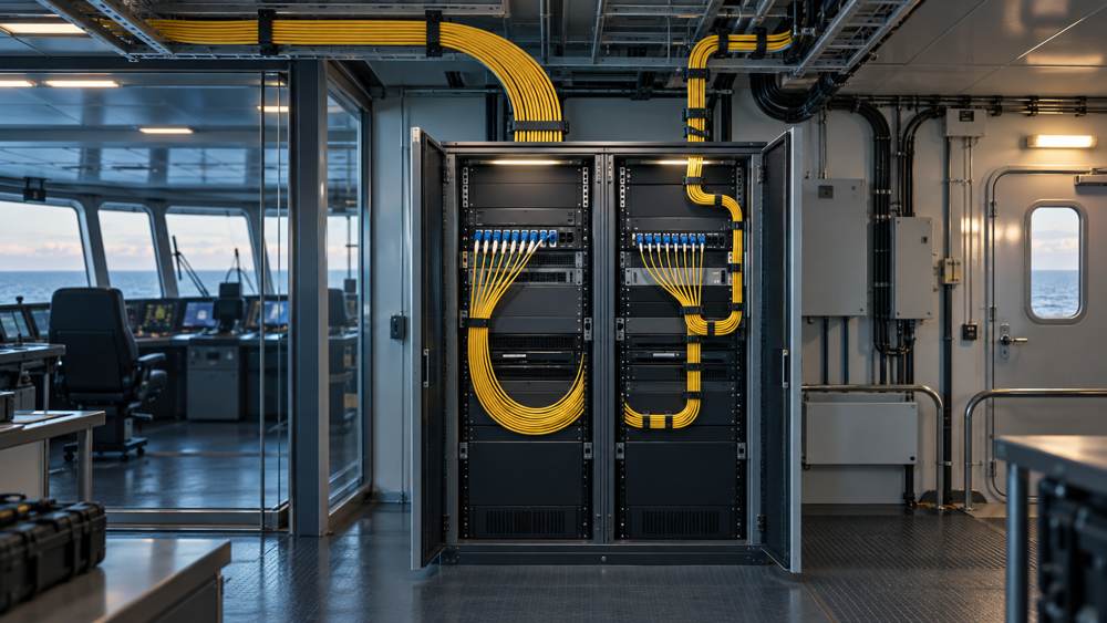
G.657.A2 provides tighter specified macrobending performance while retaining the transmission and interconnection characteristics required of G.652.D. It does not make a cable suitable for repeated flexing, and it does not establish marine or class approval. The decision belongs to the complete link and finished cable—not to the fiber label alone.
1. Start with the Link and Installation Boundary
Define what is actually being replaced
First identify whether the decision concerns a new backbone cable, a short cabinet jumper, a repair section or a retrofit extension of an existing G.652.D link. Record the endpoint equipment, optical module and connector on each side, operating wavelength, speed, route length, fiber count, installed loss budget and planned splices. A G.657.A2 replacement is not automatically useful if the limiting issue is an unsuitable connector, poor enclosure layout, damaged patch lead or excessive pulling load.
Separate fiber specification from cable duty
ITU-T G.652 and ITU-T G.657 define the relevant single-mode fiber and cabled-fiber characteristics. They do not define a shipboard cable construction. For the finished cable, IEC 60092-378:2024—now published as the corrected version incorporating Corrigendum 1:2025—covers shipboard and offshore optical fiber cables intended for fixed installation. IEC 60092-352:2025 covers cable selection and installation and explicitly separates fixed systems exposed to normal ship motion or vibration from applications involving frequent flexing.
2. Compatibility: What G.657.A2 Can Share with G.652.D
Understand Category A compatibility
The current ITU-T G.657 recommendation states that Category A requirements are a subset of G.652.D and that G.657.A fiber can be used in networks where G.652.D is specified. This supports a mixed G.652.D/G.657.A2 single-mode design at the standards level. It does not prove that two specific cable products have been qualified together, that a particular mixed splice will meet the project's event-loss limit, or that the offered cable has the required marine documents. Specify the exact fiber manufacturer and type, finished-cable part number and applicable documents.
Check the complete optical path
Confirm that both transceivers accept the proposed single-mode path at the intended wavelength, and that connectors and polish types match the equipment and patching design. Calculate channel loss from cable attenuation, connector pairs, splices and margin using supplier data and the project acceptance threshold. An A2 fiber cannot cure incompatible optics or a failed loss budget. A sensor, camera or automation device may have only copper Ethernet, PoE or serial ports; a suitable switch or gateway can provide a fiber uplink while the local device connection remains electrical.
3. Bend Performance: Where the Difference Matters
The standards do not support the shorthand claim that “G.657.A2 has a 7.5 mm cable bend radius.” They specify macrobending-loss limits for bare or uncabled fiber under defined mandrel radii, turn counts and wavelengths. The following values are maximum standard limits—not typical product performance or installed-cable bend limits.
| ITU-T requirement (08/2024) | G.652.D | G.657.A2 |
|---|---|---|
| Mode-field diameter at 1310 nm | Nominal value 8.6–9.2 µm; tolerance ±0.4 µm | Nominal value 8.6–9.2 µm; tolerance ±0.4 µm |
| Cable cut-off wavelength | ≤1260 nm | ≤1260 nm |
| Macrobending loss at 1625 nm | ≤0.1 dB at 30 mm radius, 100 turns | ≤0.1 dB at 15 mm radius, 10 turns; ≤0.2 dB at 10 mm radius, 1 turn; ≤1.0 dB at 7.5 mm radius, 1 turn |
| Macrobending loss at 1550 nm | No value in the G.652.D table | ≤0.03 dB at 15 mm radius, 10 turns; ≤0.1 dB at 10 mm radius, 1 turn; ≤0.5 dB at 7.5 mm radius, 1 turn |
| Cable attenuation coefficient | ≤0.40 dB/km from 1310–1625 nm; ≤0.30 dB/km from 1530–1565 nm | Same limits |
| Maximum PMD link design value, PMDQ | 0.20 ps/√km (M=20 cables, Q=0.01%) | Same limit |
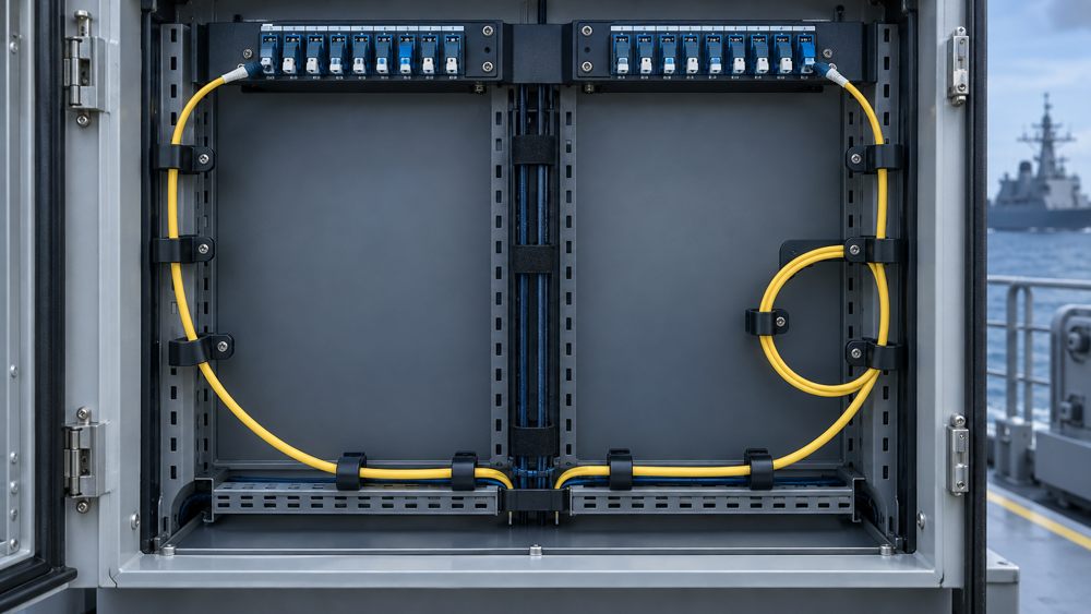
ITU-T G.657 describes A2 as appropriate for a 7.5 mm minimum fiber design radius, but that statement must be read with its specified wavelength, turn count and loss limit. It is not the allowable bend radius of a finished cable, buffer tube or patch cord. Use the cable manufacturer's stated minimum bend radius or diameter for pulling and for the installed condition; verify which condition and unit the datasheet uses. Armor, strength members, tube design, sheath and termination hardware can impose a much larger limit.
Map actual turns, not an assumed advantage
Mark cabinet entry turns, splice tray loops, patching arcs and any route that could be tightened during maintenance. If the built route already respects a G.652.D cable's documented bend limits and test margin, a switch to A2 may bring little practical benefit. If the optical layout genuinely requires compact, protected turns, A2 can be a useful candidate—but first check that the proposed complete cable and accessories fit the space.
| Decision point | G.652.D starting position | G.657.A2 starting position | Evidence required |
|---|---|---|---|
| Existing single-mode link | Retain when its route and budget meet the design | Consider for an extension with compact turns | Existing fiber record, optical modules and splice plan |
| Tight cabinet or patch tray | Rework routing if the required bend is too small | Candidate for lower bend loss at the fiber level | Finished cable and patch-lead bend limits; cabinet drawing |
| Fusion splice between categories | Category alone does not predict splice loss | Category A is compatible in principle; verify the actual pair | Fiber datasheets, splice procedure and test acceptance |
| Marine installation | Optical designation says nothing about ship suitability | Optical designation says nothing about ship suitability | Offered construction, applicable reports and class requirements |
4. Splicing a G.657.A2 Extension into G.652.D
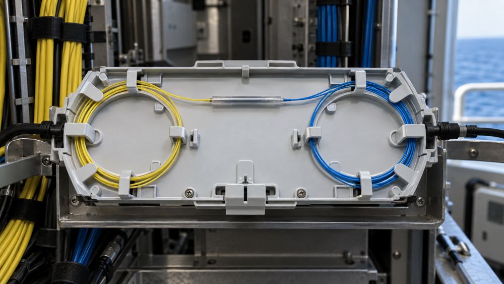
Category A compatibility makes a G.652.D-to-G.657.A2 fusion splice a reasonable engineering option, but field results depend on the particular fibers, mode-field characteristics, coating dimensions, preparation and splicer program. Ask the cable supplier for fiber data and the installer for a mixed-fiber splice procedure. Provide adequate tray capacity, splice protection, slack and labeling. Set the acceptance limit in the project test plan instead of assuming a universal loss value.
Interpret OTDR gainers correctly
An OTDR trace can show an apparent “gain” or exaggerated loss at a joint when the connected fibers have different backscatter characteristics. That trace alone does not establish the actual splice insertion loss. Test from both directions and apply the project's agreed bidirectional interpretation where individual splice-event loss is part of acceptance. EXFO's application note on OTDR gainers explains why bidirectional averaging helps. Record both raw traces and the approved result, and test the complete channel against its loss budget using the specified method.
5. Cabinet Space and Termination Design
For a bridge cabinet or machinery control rack, measure usable depth after adapters, connector boots, trays, management rings and the closed door are in place. The bend radius of the optical fiber is not the same as the workable bend radius of a buffered, jacketed patch cord or shipboard cable. Include access for inspection and cleaning and a service loop that stays within the enclosure without being crushed.
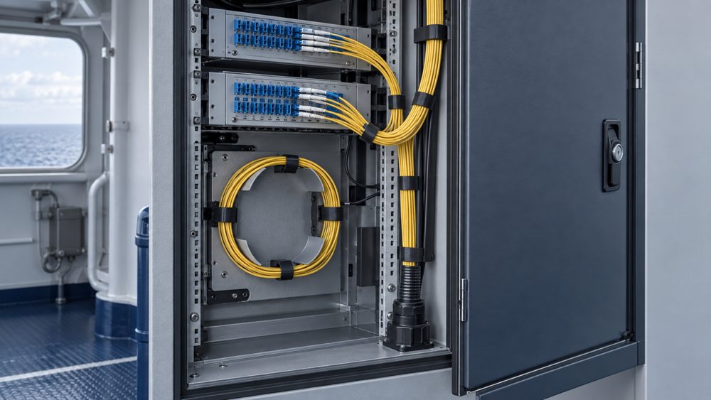
If a G.657.A2 cable has a larger or stiffer marine sheath or armor, its overall route can need more room even though its fiber has lower bend loss. Prefer a protected termination that secures the backbone cable, manages splices and uses correctly specified patch cords to reach equipment. Verify that the panel, cord, adapter and gland fit the enclosure and meet the project's environmental and fire-performance requirements. A generic indoor rack jumper should not be treated as a shipboard cable or extended onto an exposed route without evidence for that application.
6. Retrofit Decisions: Replace, Extend or Reroute?
Survey before choosing the new fiber
In a retrofit, identify every existing cable segment and termination. Capture markings and as-built drawings, inspect route access, note unavoidable turns, and measure the installed link. Verify whether the real problem is excessive bend, damaged connector, poor splice, too little cabinet clearance or absent documentation. A failed route is not automatically fixed by specifying G.657.A2; moving a termination or replacing a patch cord can be the correct design remedy.
Define the transition and downtime window
If a new G.657.A2 fixed cable section joins a G.652.D backbone, specify the splice or connector transition, spare fiber allocation, test boundaries and rollback plan. Review whether the existing enclosure has space for additional splices, whether two routes share a single failure point and whether the scheduled outage permits cleaning, testing and labeling.
7. The Certification Boundary
Three distinct claims need distinct evidence
“G.657.A2 fiber,” “cable tested to IEC 60092-378” and “a class-accepted product for this vessel” answer different questions. The first concerns the optical fiber's defined characteristics; the second concerns a particular shipboard cable construction and applicable testing; the third depends on the project, the issuing society or authority and the scope of a valid certificate. A fiber supplier's datasheet cannot replace a finished-cable report, and an approval for another sheath, armor or fiber-count variant should not be applied to the quoted part number.
Ask what the exact offer covers
Request the cable drawing, material and fiber identification, applicable IEC edition, test-report references, certificate number and scope, manufacturing site, validity and listed variants. State the required sheath material and tests rather than relying on the words “marine” or “LSZH.” Depending on the project, the specification may need to identify the applicable material requirements in IEC 60092-360 and the required flame-spread, smoke and halogen-acid-gas test standards and acceptance criteria. Also state required oil, moisture, UV, mud, mechanical or fire-resistance performance where relevant.
IACS explains that it does not certify products or issue Type Approval certificates; individual member societies apply their own rules and are not obliged to accept another member's certificate. The vessel's nominated class society, flag requirements and project specification therefore determine the evidence needed.
8. Recommended Decision Workflow and Architecture
Choose the fiber where it changes the outcome
- Confirm service requirements and endpoint optics.
- Map the cable route, bends and fixed-versus-moving sections.
- Calculate the installed loss budget.
- Identify the existing fiber and planned joints.
- Compare complete G.652.D and G.657.A2 cable constructions.
- Verify installation, fire and class documents.
- Approve the installation and acceptance-test plan.
If both constructions pass, choose on installation fit, availability, lifecycle spares and project procurement criteria. Do not infer a speed, service-life or reach improvement from A2 alone.
Apply an architecture only after interface review
A practical starting architecture is: local Ethernet/PoE or serial devices → protected switch or gateway → patch panel → fixed single-mode shipboard backbone → protected panel → remote switch or control rack. An existing G.652.D segment may remain in service when its measured performance and route are acceptable, while a new compact segment can use a properly qualified G.657.A2 cable. Vessel-to-shore connectivity is a separate system design and may use satellite, radio, cellular or a physical shore connection when berthed.
| Design choice | Appropriate starting condition | Recheck or reject when |
|---|---|---|
| Keep existing G.652.D | Route, bends, interfaces and measured loss already pass | A new compact route violates the finished cable's bend instructions |
| Add a G.657.A2 fixed segment | Tight protected route and valid mixed-splice/test design | Cable construction, certificate scope or installation method is unknown |
| Change patching, not backbone | Trouble is confined to a cabinet or lead | A backbone defect or insufficient fixed-route protection remains |
| Use a specialized moving cable | Route crosses repeated motion | Only a fixed-installation cable has been proposed |
9. Common Mistakes and Verification Checklist
Do not write “7.5 mm cable bend radius” solely from the G.657.A2 designation. Do not assume all G.657 categories carry the same G.652.D compliance claim; Category B fiber is not necessarily G.652.D-compliant even though it may be system-compatible in defined access-network applications. Do not treat a one-way OTDR gainer as negative physical splice loss. Do not use a generic class logo, an ISO 9001 certificate or a certificate for a different construction as proof that the quoted finished cable is approved.
| Gate | What to verify | Record to retain |
|---|---|---|
| Design freeze | Endpoint optics, fibers, route zones, bend limits, loss budget | Approved link drawing and equipment schedule |
| Purchase order | Exact cable code, construction, fiber variant, reports, approvals | Supplier offer, datasheet and document register |
| Installation | Pulling and service bend limits, splice map, closed-door clearance | As-built route, fiber IDs and inspection photos |
| Handover | Agreed insertion-loss and OTDR methods, both directions where required | Wavelength-specific results, traces and sign-off |
10. RFQ Inputs and Frequently Asked Questions
Send a comparison-ready enquiry
Include the ship or platform, project phase, destination and end use; existing fiber type and test records; link endpoints and optical interfaces; route length and zones; bends, cabinet dimensions and moving sections; fiber count and spares; termination and splicing plan; sheath, armor, flame, smoke, halogen, oil and moisture requirements; nominated class society and document list; test methods, quantities, cut lengths and delivery schedule.
Frequently asked questions
Can I splice G.657.A2 to existing G.652.D fiber?
Yes. Category A is compatible at the standards level. Confirm the actual fibers, mixed-fiber splice procedure and measured acceptance result for the project.
Does G.657.A2 always reduce installed link loss?
No. Its advantage concerns bend-loss behavior under defined conditions. Connectors, splices, route length and the complete cable can dominate the installed link budget.
Can I bend a G.657.A2 marine cable to 7.5 mm?
The fiber designation alone does not establish that cable bend radius. Check the finished cable or cord manufacturer's minimum bend limits for pulling and installed conditions.
Do my single-mode transceivers need changing?
Not solely because the new fiber is Category A. Verify module specifications, wavelength, channel budget, connector and project acceptance requirements.
Why does one OTDR direction show a gain at a mixed splice?
Different backscatter characteristics can create an apparent gainer. Use the specified bidirectional method before judging event loss.
Is G.657.A2 automatically a class-approved marine cable?
No. Fiber designation, finished-cable test evidence and any required class approval must be checked separately for the quoted construction.
Should every retrofit replace G.652.D with G.657.A2?
No. Survey the defect and route first. Repair, rerouting or a patching change may resolve the issue while a suitable G.652.D backbone remains in service.
Prepare a Shipboard Fiber Comparison
Send the existing link record, route and zone map, cabinet constraints, required certificates, fiber count, cut lengths and test requirements. ZION can compare eligible cable constructions and confirm the documentary scope against the exact offered part number.
Request Project Support


