Introduction to fiber optical pigtails
Author: Site Editor Publish Time: 12-08-2021 Origin: Site
Fiber Optic Pigtails: Types, Polishes and Selection Guide Learn how fiber optic pigtails terminate installed cable, how connector and polish choices affect compatibility, and what to specify before ordering.
A fiber optic pigtail is a short length of optical fiber with a factory-installed connector on one end and an unterminated fiber on the other. The bare end is normally fusion-spliced to a fiber in an installed cable, while the connectorized end plugs into an adapter, patch panel or compatible optical interface. This arrangement brings factory-controlled connector termination into the field without requiring the installer to polish a connector on the cable.
■What Is a Fiber Optic Pigtail?
The defining feature is the one-ended construction: one connector and one splice-ready fiber end. Most common pigtails use a single-fiber connector such as LC, SC, FC or ST. They may be supplied individually or as color-coded multi-fiber sets for termination inside an optical distribution frame, enclosure or splice tray.
Pigtail vs patch cord: a pigtail has a connector on one end and is intended to be spliced. A patch cord normally has connectors on both ends and is intended to make a removable equipment or panel connection. A splice-on connector is another termination option in which a factory-polished connector and short stub are attached directly by a mechanical or fusion splice.

■How Fiber Pigtails Terminate an Installed Cable
A typical termination sequence is straightforward, but the quality of every step affects the completed link:
Prepare and identify the cable fibers according to the approved splice plan.
Strip, clean and cleave the selected cable fiber and the unterminated end of the pigtail.
Fusion-splice the two fibers using the correct splicer program for the fiber types.
Protect the splice and route it in the tray without violating the component manufacturer's bend-radius limits.
Inspect and clean the connector end face before mating, then test and document the completed link.
The pigtail does not remove the splice from the optical loss budget. Connector loss, splice loss, fiber attenuation and any splitters or other passive components must all be included when evaluating the finished channel.
■Common Connector Types
Connector choice is determined by the adapter, patch panel and equipment interface—not by a general ranking of connector quality. IEC 61754 contains standardized interface families, while the exact optical and mechanical performance still belongs to the specified product.
LC: a compact connector widely used where port density is important, including many transceiver and patch-panel interfaces.
SC: a push-pull connector commonly found in telecommunications, access networks and optical distribution equipment.
FC: a threaded connector still used in some measurement, laboratory, telecom and vibration-sensitive installations.
ST: a bayonet-style connector associated with many legacy premises, industrial and instrumentation systems. Confirm the installed interface before specifying it for a new project.

■UPC vs APC: Choose by Reflectance and Compatibility
UPC and APC describe different physical-contact end-face geometries. APC uses an angled end face to direct reflected light away from the fiber core, so it is selected where low reflectance is important, including many PON, analog video, RF-over-fiber and wavelength-sensitive systems. UPC remains common in data communications and other systems whose interfaces are specified for UPC.
Do not mate APC and UPC connectors. Their end-face geometries are incompatible, and mating them can create excessive loss or damage. Match the pigtail polish to the adapter path and the equipment interface. APC's principal advantage is lower reflectance; it should not be described as automatically having lower insertion loss than UPC.
■Single-Mode and Multimode Fiber Options
The pigtail fiber must match the installed fiber and the optical system. Single-mode pigtails commonly use fiber conforming to ITU-T G.652.D or bend-insensitive ITU-T G.657 categories. G.657.A1 and G.657.A2 are designed for improved macrobending performance and remain compatible with G.652.D transmission characteristics, but the exact fiber designation and minimum bend radius must be checked on the product datasheet.
Multimode pigtails may use OM1, OM2, OM3, OM4 or OM5 fiber. OM1 is normally 62.5/125 µm; OM2 through OM5 are 50/125 µm graded-index categories. Do not select only by jacket color. Confirm the printed designation, datasheet, installed cable records and transceiver requirements because color conventions can vary by region, product construction and manufacturer.
■Fiber Count, Buffer and Jacket Construction
A simplex pigtail terminates one fiber. Multi-fiber pigtail sets—often supplied as 6-, 12- or 24-fiber assemblies—can simplify high-density splice work and fiber identification. The required count should follow the cable design, tray capacity, color-coding plan and spare-fiber strategy rather than a fixed bundle size. ZION's current bunch fiber optic pigtail configurations illustrate common LC, SC and other connector options for multi-fiber termination.
For protected splice trays, 0.9 mm buffered or unjacketed pigtails are common because they occupy little space. Jacketed 2.0 mm or 3.0 mm constructions provide more handling protection where the pigtail must route outside a protected tray. The product's strain relief, buffer type and routing method should match the enclosure.
PVC and low-smoke, zero-halogen compounds describe different jacket-material approaches. OFNP is a North American plenum listing, not simply another jacket material. Specify the required fire-performance classification under the applicable building code, project standard and authority having jurisdiction; a generic “LSZH” request does not by itself define a complete fire rating.
■How to Specify a Fiber Optic Pigtail
A procurement description should identify more than the connector name. Include:
connector family and polish, such as LC/UPC or SC/APC;
single-mode or multimode category, including the exact fiber designation;
simplex or multi-fiber count and the required color sequence;
buffer or jacket construction, outside diameter and fire-performance requirement;
finished length, tolerance and packaging or labeling requirements;
insertion-loss and return-loss acceptance criteria, test wavelength and requested test report;
operating environment and any project-specific mechanical or compliance requirement.
For a repeatable RFQ description, the fiber patch cord and pigtail specification generator can organize connector, polish, fiber, jacket, diameter and length selections into one line. The generated description should still be reviewed against the equipment interface and project requirements.
■Installation, Inspection and Testing
Connector cleanliness is essential. Inspect the end face using suitable equipment, clean it when contamination is present and inspect it again before mating. A protective cap does not prove that a connector is clean. Keep the connector capped when it is not in use, and never look into a fiber or connector unless the optical source has been safely controlled.
After splicing and routing, test the completed cable plant at the wavelengths and by the method required for the project. An optical loss test set is used for end-to-end insertion-loss acceptance. OTDR testing can characterize splice events and help locate faults, but it does not replace end-to-end loss testing. Record the method, reference configuration, wavelengths, direction where required and final results.
■Common Selection Mistakes
Ordering by connector family alone: LC, SC, FC or ST does not define polish, fiber type, length or construction.
Mixing UPC and APC: matching connector bodies do not make different end-face geometries compatible.
Treating color as the specification: color helps identification but does not replace a verified fiber and polish designation.
Ignoring the enclosure: pigtail diameter, bundle size, bend radius and splice-protector arrangement must fit the tray.
Accepting a connector by appearance: cleanliness inspection and optical testing address different risks and both may be required.
■Fiber Optic Pigtail FAQ
Is a fiber optic pigtail the same as a patch cord?
No. A pigtail has one connectorized end and one splice-ready end. A patch cord normally has connectors on both ends for removable interconnection.
Can an APC pigtail connect to a UPC adapter or device port?
The complete mated interface must use the required polish. APC and UPC connector end faces should not be directly mated, even when their connector bodies fit the same adapter family.
Should a pigtail use the same fiber as the installed cable?
Yes, the pigtail fiber category and geometry should be compatible with the installed fiber and optical system. Confirm the exact designations rather than relying only on “single-mode” or “multimode.”
What test information should be requested with pigtails?
Specify the applicable insertion-loss and return-loss criteria, test wavelengths, connector grade or product standard when required, and whether individual serialized results are needed. Acceptance values should come from the project specification and the selected product datasheet.



 Fiber Optic Tools
Products 6 families
Solutions 6 markets
Resources Tools & docs
Certificate
Certification and compliance references for project review, qualification and purchasing documentation.
 Fiber Optic CableAccess and backbone
 Ethernet CableCat5e to Cat8
 Coaxial CableRF and video signal
 Fire, Security & AlarmSafety systems
 Voice, Audio & VideoSignal cabling
 Power & Control CableEnergy and control
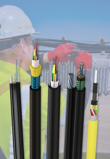
Fiber optic cable systems
Outdoor, indoor, FTTH and distribution cable lines for access networks, backbone routes and campus deployments.
 Telecom & ISP NetworksFTTH, PON, ODN
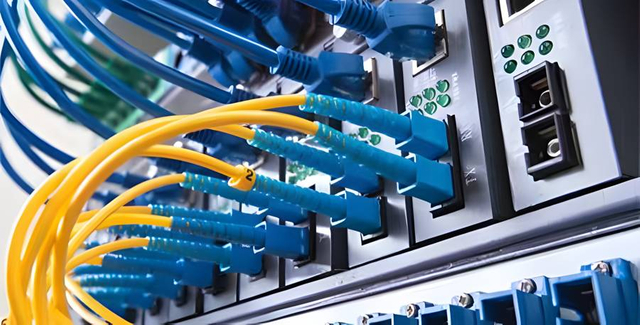 Data Center InfrastructureServer room cabling
 Building Low-Voltage SystemsBMS, AV, weak current
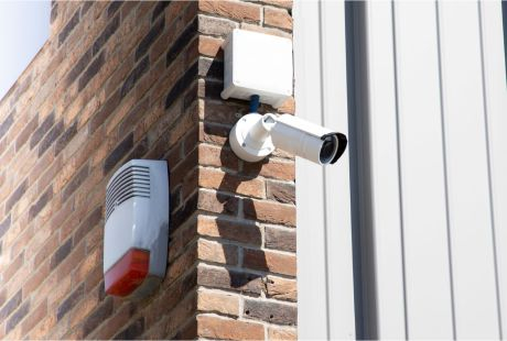 Security & Fire ProtectionAlarm, CCTV, access
 Industrial Automation CablePLC, RS485, fieldbus
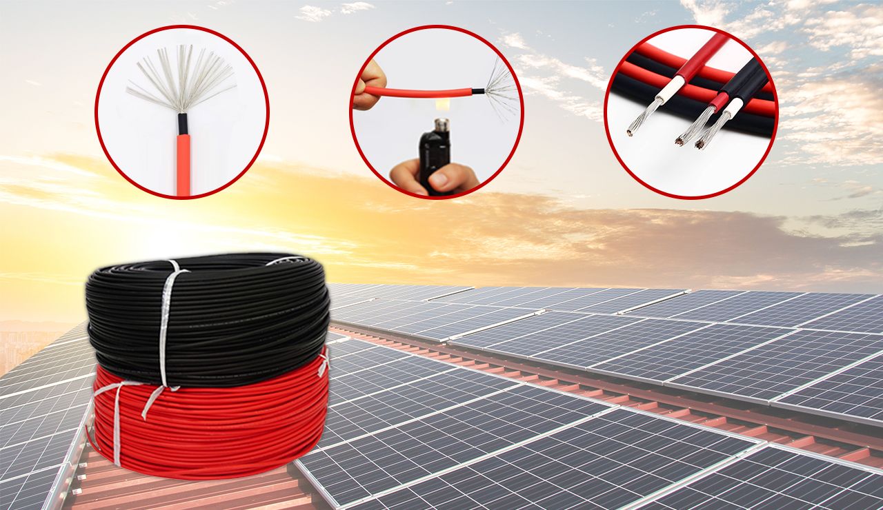 Energy & Power InfrastructureSolar, battery, power
Telecom & ISP Networks
For FTTH / PON access, outdoor fiber deployment, aerial routes, duct routes, direct burial routes, rural broadband and ODN planning.
Tools
Use calculators and planning tools for conduit capacity, PoE voltage drop and fiber optic link loss budget work.