
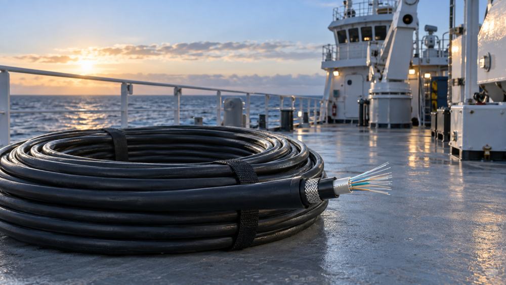
1. Start with the Project Requirement and Installation Boundary
Identify the service and its endpoints
List each connection: for example, bridge to data rack, machinery control room to switch cabinet, or a monitoring concentrator to the vessel network. Record the equipment at both ends, actual optical port or transceiver type, required speed, connector, redundancy requirement and expected upgrade path. A camera or sensor does not automatically require a fiber connector: the local leg may still use Ethernet copper, PoE or a serial interface, with fiber carrying traffic only between switches or concentrators.
Separate fixed cable from moving cable
Mark the permanently supported route and every moving or repeatedly flexed section. IEC 60092-378:2024, now available as a corrected version incorporating Corrigendum 1:2025, applies to shipboard and offshore optical fiber cables intended for fixed installations. IEC 60092-352:2025 covers selection and installation conditions for shipboard cables, including fiber. It treats normal vessel vibration and motion as fixed-system service, but excludes cables intended for frequent flexing. Retractable thrusters, elevators, moving decks, cranes and shore connections are examples where a cable designed for the defined motion and environment is required.
2. Map Installation Zones Before Selecting a Cable
Draw a route-by-route zone schedule
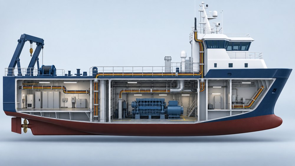
Break a long run into segments: protected accommodation or equipment room; machinery or utility space; transition through bulkheads or decks; and exposed or washdown-prone deck. For each segment, document heat, oil or chemicals, moisture, salt spray, impact, cable crowding, access for replacement and whether the route passes a fire boundary. These are project inputs, not proof that every cable carrying a “marine” label suits every zone.
Put the harshest segment on the drawing
A single exposed portion can govern sheath, protection and termination details for the whole route—or justify separate cable constructions joined at a planned termination point. Show glands, conduit or tray, protected slack, bend constraints and watertight or fire-rated penetrations on the installation drawing. An armored cable alone does not make a penetration watertight or fire resistant.
| Route input | Initial direction | Decision to verify |
|---|---|---|
| Protected rack-to-rack run | Fixed shipboard construction; match the required fire and smoke performance | Is the complete route protected, and what does the project cable schedule require? |
| Crowded machinery route | Examine sheath resistance and mechanical protection | Which oil, temperature, abrasion and impact tests apply to the exact cable? |
| Exposed or wet route | Evaluate moisture protection, sheath suitability and termination sealing | What ingress, UV, salt or weather exposure is specified? |
| Tight patching or cabinet turns | Consider bend-insensitive single-mode fiber and suitable patch cords | Does the finished cable's installed bend radius fit the layout? |
| Repeatedly flexed section | Escalate to a cable designed and qualified for that motion | What bending cycles, travel and tensile loads are required? |
3. Choose Single-Mode or Multimode from the Optical Interfaces
Match the optics and link budget first
Ask for the switch and transceiver specifications at both ends. Confirm wavelength, supported fiber category, connector interface and the transceiver manufacturer's reach for the selected data rate. Single-mode is often a sensible backbone candidate where routes may be extended or upgraded; multimode can be appropriate for a controlled short link using compatible multimode optics. Neither is universally superior. Build the loss budget from the specified cable attenuation, connector pairs, splices and an agreed engineering margin, then compare that total with the transceiver budget. Do not substitute a generic reach value for this calculation.
Understand what G.657.A2 does—and does not—say
The in-force ITU-T G.657 (08/2024) recommendation identifies G.657.A2 as appropriate for a 7.5 mm minimum design radius and specifies uncabled-fiber macrobending performance at defined radii, wavelengths and turns. That 7.5 mm value is a fiber-level design and test reference; it is not the minimum installation bend radius of a finished shipboard cable. Use the cable manufacturer's static and installation bend limits for the exact construction and diameter. G.657.A2 also does not demonstrate IEC 60092-378 conformity or class approval. For multimode links, specify the fiber category required by the transceiver and cabling design rather than relying on the generic phrase “50/125 µm multimode.”
4. Specify LSZH and Fire Performance Precisely
Treat LSZH as a set of test requirements
“LSZH” is useful procurement shorthand, but it is not a complete performance specification. IEC 60754-1 determines halogen acid gas content from materials used in cable construction, while IEC 60754-2 determines the acidity and conductivity associated with gases from cable materials. IEC 61034-1 specifies the smoke-density test apparatus; the test procedure and recommended evaluation requirements are in IEC 61034-2. State the required standard parts, editions, acceptance criteria and report identifiers. A sheath-material description alone does not demonstrate the fire behavior of the offered cable construction.
Keep flame spread and fire survival separate
A single-cable flame propagation result under IEC 60332-1-2 does not establish performance for vertically installed cable bunches. Where the cable schedule requires bunched-cable flame performance, specify the applicable category from the IEC 60332-3 series and verify that the report covers the offered cable construction and the stated non-metallic-material volume. Functional integrity during fire is a separate requirement again. IEC 60092-378 includes optical cable types designed for that duty, but the route, required duration, test method and acceptance criterion must be defined by the vessel fire strategy and applicable class rules.
5. Decide Whether Armor Is Necessary
Base mechanical protection on the installation method
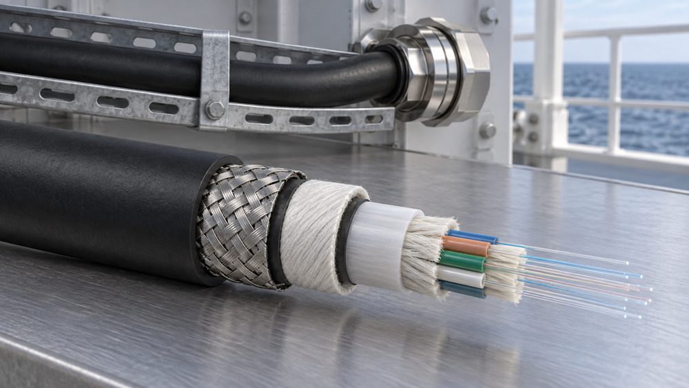
Armor may be justified where exposed cable faces crushing, abrasion, impact or installation damage. It can also increase diameter, weight, stiffness and termination complexity. For a protected conduit or tray run, another construction may fit the route better. Compare the supplier's documented tensile, crush, impact and bend values against the actual installation method; “armored” alone is not a mechanical rating.
Check metal components and terminations
Where metallic armor or other metal elements are proposed, identify the armor material, gland or termination arrangement, corrosion compatibility and required bonding or earthing treatment under the vessel's approved electrical design. Do not infer a one-end or two-end bonding scheme from the word “armored.” The specification should state whether the construction is metallic or all dielectric and compare the documented tensile, crush, impact and bend performance with the installed route.
6. Translate the Environment into Verifiable Requirements
Specify exposure, not just “marine grade”
State the service and installation temperature ranges, intermittent heat sources, oil or chemical contact, UV exposure, water or humidity, and any washdown conditions. Identify where the cable will be protected by enclosure or conduit and where its outer sheath is directly exposed. IEC 60092-360 covers characteristics of insulating and sheathing materials used in shipboard and offshore cable applications; the exact compound and supporting test evidence still have to match the requested exposure.
Protect the entire installed channel
Cable, patch cords, connectors, glands and splices form a system. A suitable outer sheath does not protect an unsealed connector on an open deck. Locate termination points in appropriate enclosures, provide strain relief, control bend radius at entries and document inspection access. If fiber supports structural monitoring, distinguish an ordinary communications link from fiber Bragg grating (FBG), distributed acoustic sensing (DAS), distributed temperature sensing (DTS) or other sensing systems, which require application-specific fibers, interrogators and validation.
7. Ask for the Right Class and Product Documents
Separate a standard claim from product approval
Request the exact offered part number, datasheet, cable drawing and construction code. Ask for a compliance matrix against IEC 60092-378:2024, including the corrected text incorporating Corrigendum 1:2025, together with the supporting reports and any project-required class or type-approval certificate. Each report or certificate should identify the cable family, construction, manufacturing site and limits it actually covers. A company-management certificate, an optical-fiber datasheet and a certificate for another cable variant are not evidence for the quoted finished product.
Verify certificate scope before purchase
Check the issuing body, certificate number, validity, manufacturing site, covered construction and all limitations. The owner's specification, flag administration and selected classification society can require different evidence. IACS confirms that it does not certify products or issue type-approval certificates, and one IACS member is not automatically required to accept another member's certificate. Use the rules and approval database of the society selected for the vessel. IACS UR E10 Rev.10 is a type-approval test specification for electrical, electronic and programmable equipment; it should not be presented as generic proof of passive optical-cable compliance.
| Document or evidence | What it can establish | What it does not establish by itself |
|---|---|---|
| IEC 60092-378 compliance matrix and reports | Construction and test evidence mapped to the shipboard optical-cable standard | Automatic acceptance by every owner, flag or classification society |
| Classification-society type-approval certificate | Approval scope stated by that society for the listed product family, site and conditions | Coverage of an unlisted variant, expired certificate or another manufacturing site |
| Fiber manufacturer's G.657 or multimode datasheet | Optical-fiber category and fiber-level attributes | Finished-cable fire, mechanical, environmental or marine approval |
| ISO 9001 or company quality certificate | A certified quality-management system within its stated scope | Product conformity or vessel-specific acceptance |
8. Build an RFQ That Can Be Quoted Correctly
Provide a route schedule and a document schedule
For each link, identify the ship or platform type, design or retrofit stage, endpoints, route length, zones crossed, installation method, fiber count and spare capacity. Supply the equipment interfaces and connector requirements. A route schedule prevents one generic cable description from hiding different exposures; a document schedule lets the supplier confirm what evidence can be supplied with the specific offer.
Specify commercial and handover details
Include required drum length or cut lengths, installation location, destination country, end user and end use, delivery date, labeling, packing and acceptance documents. State whether patch cords, pigtails, panels or glands belong in the bill of materials. This gives the supplier enough context to review the cable and associated termination scope together.
9. A Recommended Specification and Decision Workflow
Use one sequence for every link
Typical internal architecture: device or local copper/serial segment → suitable switch or gateway → protected optical termination → fixed shipboard fiber backbone → protected termination → remote switch or control equipment. Adapt this sequence to the approved network topology, redundancy philosophy, equipment interfaces and environmental zoning.
- Confirm the function, endpoint equipment and optical interfaces.
- Measure the installed route and classify each zone and any moving section.
- Choose fiber type and count from optics, loss budget and future capacity.
- Define cable construction: sheath, fire behavior, moisture protection and mechanical protection.
- Review terminations, penetrations, support, bending and maintenance access.
- Lock the required standard editions, class documents and acceptance tests into the RFQ.
Know when the baseline architecture does not apply
| Recommended starting point | Suitable when | Redesign when |
|---|---|---|
| Fixed fiber backbone between protected cabinets | Equipment offers compatible optics or gateways; route is permanently supported | Route has repeated flexing or an unaddressed deck exposure |
| Single-mode backbone with planned spare fibers | Future endpoints or long, variable routes justify the choice | Installed optics and approved design require multimode; interfaces are not checked |
| Local copper/PoE with fiber uplink | Devices have only electrical ports and a nearby powered switch | No suitable enclosure, power, environmental rating or copper run design exists |
10. Common Mistakes and an Acceptance Checklist
Avoid shorthand that hides a design decision
Common errors include treating G.657.A2 as a marine cable approval, using an LSZH label in place of reports, ordering armor without checking glands and minimum bend radius, and copying an optical reach from a transceiver sheet without counting connection loss. Another mistake is extending a fixed-installation cable through a moving assembly. Resolve each issue on the drawing and RFQ before purchase.

Check the delivered system against the approved schedule
| Stage | Check | Evidence to keep |
|---|---|---|
| Before ordering | Part number, construction, fiber type/count, zone fit, reports and required approvals | Signed cable schedule and supplier document register |
| On receipt | Drum ID, marking, quantity, visible damage and matching certificate scope | Packing list, drum record and received inspection |
| After installation | Route, support, penetrations, strain relief, bends and termination labels | As-built drawings and inspection record |
| Optical acceptance | Agreed test direction, wavelengths, reference method, attenuation/return-loss limits where applicable, end-face inspection and polarity | Results linked to fiber IDs, equipment settings, launch/receive cords and approved criteria |
For installed links, the project can reference IEC 61280-4-1 for multimode attenuation measurements and IEC 61280-4-2:2024 for single-mode attenuation and optical return loss measurements. IEC 61300-3-35:2022 provides connector end-face inspection criteria, but inspection does not replace optical performance testing. The contract should state which methods apply and the pass limits derived from the approved link budget.
11. RFQ Inputs and Frequently Asked Questions
Copy these inputs into the enquiry
Vessel/platform and stage: ____ · End user/end use and destination: ____ · Link endpoints and route: ____ · Zone exposures and moving sections: ____ · Route length and required cut lengths: ____ · Equipment ports, speed and optics: ____ · Single-mode/multimode, fiber count and connector: ____ · Sheath, fire/smoke, oil/moisture/UV requirements: ____ · Armor and installation method: ____ · Class society and required documents: ____ · Panels, patch cords and tests: ____.
Frequently asked questions
Is every G.657.A2 cable suitable for a ship?
No. G.657.A2 identifies bend-loss-insensitive single-mode fiber. Its 7.5 mm minimum design radius is a fiber-level reference, not the installation bend radius of a finished shipboard cable. Verify the complete cable construction, declared bend limits and marine evidence separately.
Is multimode acceptable onboard?
It can be when the endpoint optics, reach, link budget and project specification support it. Confirm the grade and transceivers before ordering.
Does LSZH mean the cable will keep operating during a fire?
No. Smoke and gas behavior, flame propagation and circuit integrity are distinct requirements with distinct evidence.
Should every exposed run use armor?
Not automatically. Match impact, crush, corrosion, diameter, bending and termination needs to the route and consider other physical protection.
Can standard shipboard fixed cable run through a moving assembly?
Do not assume so. Define the motion and obtain a cable design qualified for the relevant flexing duty.
Can a non-optical device connect to a fiber backbone?
Yes, through a suitable switch, media converter or gateway selected for its interface and environment. Check power and enclosure requirements.
Is a company quality certificate enough for class approval?
No. Request product-specific evidence covering the offered construction and have the project team confirm the relevant class requirements.
What should be tested at handover?
Follow the approved acceptance plan. Identify every fiber, test direction, wavelength, reference method and pass limit; inspect connector end faces, verify polarity, and compare measured attenuation and return loss where specified with the approved link budget. IEC 61280-4-1, IEC 61280-4-2:2024 and IEC 61300-3-35:2022 are relevant references when adopted by the project.
Prepare a Project-Specific Marine Fiber Cable Review
Send the route schedule, equipment interfaces, cable quantities, environmental exposures, required standards, destination and document list. ZION can review the proposed cable specification, associated termination items and quotation scope for the defined project.
Request Project Support


