

1. First Confirm Which Data Layer Is Being Transported
What teams call “camera data” or “radar data” can represent very different transport conditions. Compressed video, raw images, point clouds, target lists, and device status may use different interfaces, data rates, and synchronization methods.
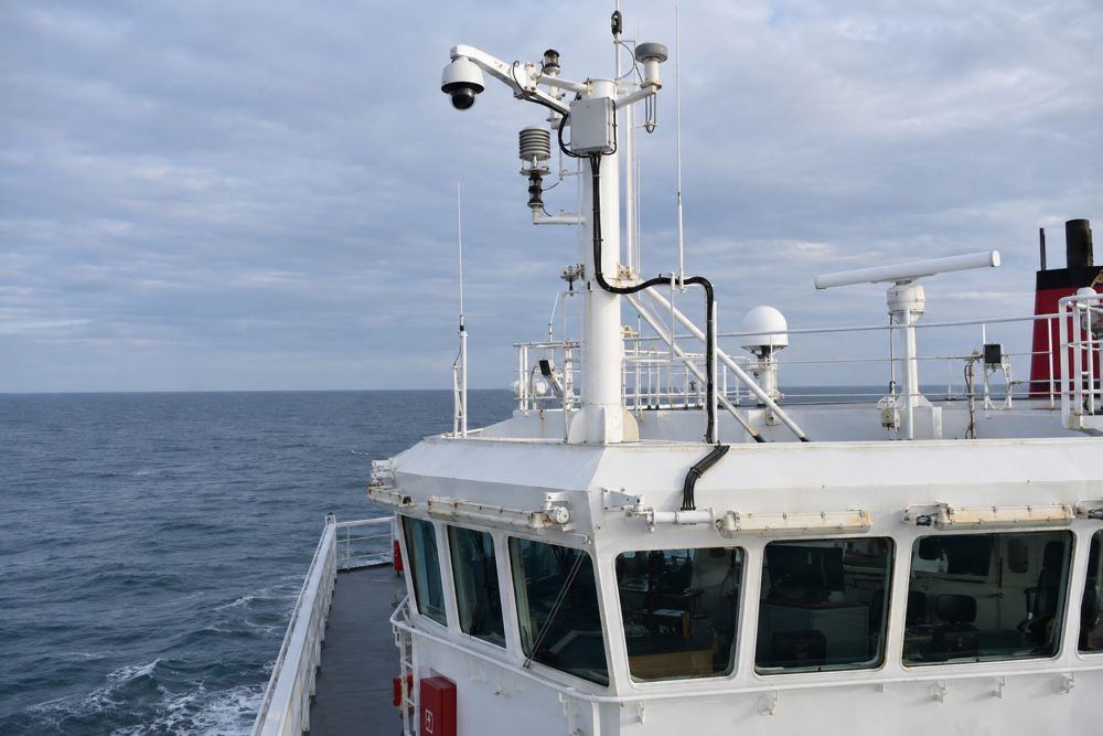
Request the output interface, protocol, operating modes, typical and peak data volume, and time-synchronization requirements from the equipment supplier. Device count, pixel count, or the label “AI sensor” is not enough to calculate bandwidth.
If processing occurs locally, the return traffic may contain only detection results and compressed video. If an onboard compute node needs raw data, the link demand can be much higher. The equipment output mode is an input to the fiber design.
2. Choose Between Direct Connections and Local Aggregation
The access method depends on device interfaces, nearby power, maintenance conditions, and the impact of a shared point of failure.
| Access method | Suitable condition | Fiber configuration focus |
|---|---|---|
| Native optical port | The device already has a compatible optical interface | Match fiber type, wavelength, connector, and module |
| Local multi-device aggregation | A switch and suitable power are available nearby | Uplink capacity, endpoint protection, and maintenance space |
| Single-device media conversion | The device has an electrical port and the conversion method is approved | Converter interface, power, environment, and failure behavior |
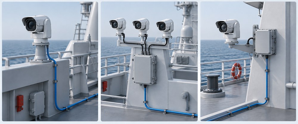
Local aggregation can reduce the number of independent long-distance links for nearby devices, but the aggregation switch becomes a shared component. The overall system design should determine whether dual nodes, independent power, or redundant paths are necessary.
A media converter for one device adds an active component and a power point. It is useful only when the distance, environment, or interface requirement justifies the added equipment.
3. Fiber Backhaul Does Not Mean Remote Power
A common candidate architecture connects devices over copper to a local PoE switch and uses the switch optical port for backhaul. PoE exists only on the local copper segment; it does not pass through the pure fiber uplink to the bridge. The switch power supply, environmental rating, and failure impact still need separate consideration.
If suitable power is not available at the mast, confirm the source, voltage drop, protection, backup power, and installation position. ZION can then match the fiber structure, length, and termination configuration to the confirmed equipment and power layout.
Short copper links may remain appropriate when an existing cable already meets both data and power needs. A change to fiber should be based on interference, distance, maintenance, and system-boundary requirements.
4. Size Uplink Capacity for Real Operating Modes
The backhaul must cover the services that operate at the same time, not only the nominal rate of one device. When video devices and other sensors share an aggregation node, calculate concurrent traffic, bursts, network overhead, and the margin accepted by the project.
Check raw-data upload, playback, and multi-device concurrency separately instead of substituting normal compressed-video traffic.
1G or 10G depends on ports, modules, switching equipment, and the link. Higher cable specifications or more fibers do not automatically raise the speed of one Ethernet link.
Time synchronization, multicast, real-time behavior, and fault detection must be validated across switches, converters, and application protocols.
Capacity margin should correspond to known bursts, future services, or project rules rather than an unexplained multiplier.
5. Separate Exposed Terminations from Cabinet Terminations
An LC/UPC connection in a dry onboard cabinet does not face the same protection conditions as a connection on an exposed deck. Even with the same internal optical interface, the exposed endpoint also needs an enclosure, cable entry, sealing, retention, and maintenance protection.
- Can technicians inspect and clean the connector without removing adjacent equipment?
- Does the retention structure carry cable tension instead of the connector?
- Does the cable entry match the cable diameter, and is there controlled space for slack and bend radius?
- Can the intended protection level be restored after opening the enclosure?
- Where can the link be disconnected during mast removal, and how will contamination be prevented?
A waterproof connector is only one part of the protection chain. Evaluate the connector, cable entry, strain relief, sealing, and restoration after maintenance as a complete assembly.
6. Select Fiber by Checking Equipment at Both Ends
A practical sequence is: equipment interface → single-mode or multimode → wavelength and module → connector and polish → cable and route.
For a new single-mode link, G.652.D or G.657.A2 may be considered. In the current ITU-T G.657 (08/2024), category A fibers are compatible with G.652.D. However, improved macrobending performance of the fiber does not mean the complete cable, breakout, or connector boot can be bent to any small radius. Follow the installation bend radius, long-term bend radius, and tensile limits of the selected cable product.
Matching connector shapes do not guarantee compatibility. Confirm polish type, port requirements, polarity, and the transmit/receive configuration at both ends. A single-fiber bidirectional module also requires complementary wavelengths and the correct pair.
The optical budget should include cable, connector, and splice loss while checking both receiver sensitivity and overload limits. A module rated for a longer distance is not automatically better for a short onboard link.
7. Complete Post-Installation Checks at Two Layers
Optical checks include connector end-face condition, polarity, continuity, and end-to-end insertion loss. OTDR may support location and documentation when appropriate. On short links, account for instrument dead zones and the selected test method.
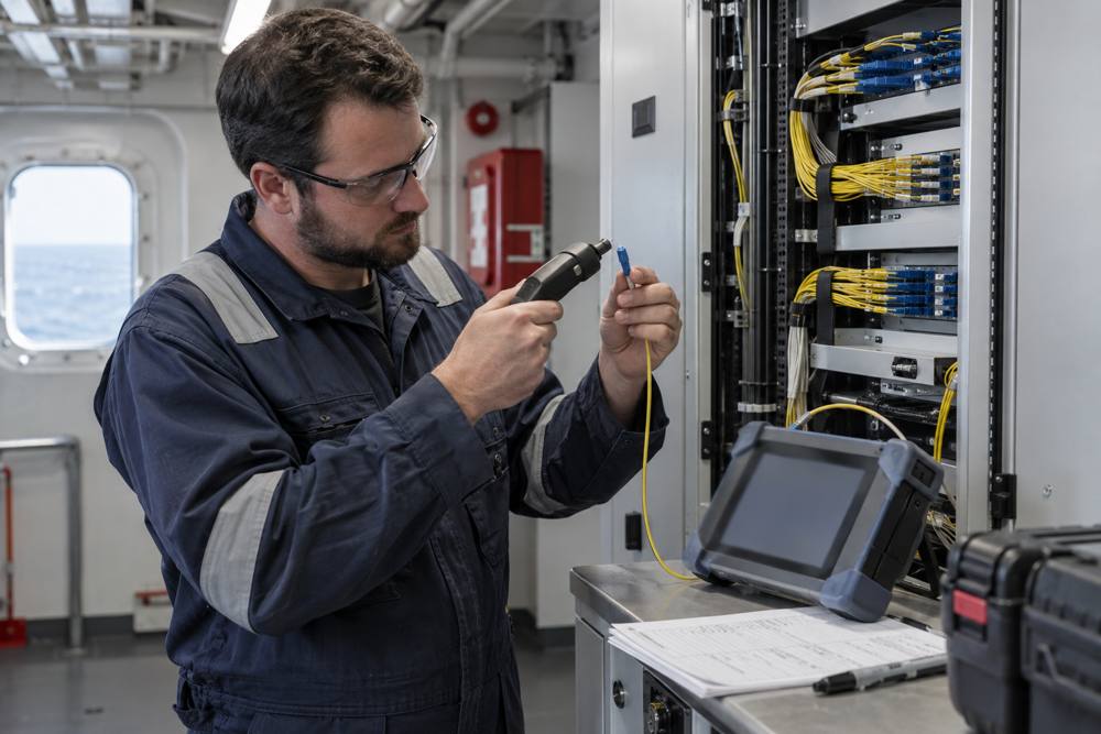
System checks confirm interoperability, load, synchronization, power-loss recovery, and fault behavior under actual video and data modes. Optical tests verify the fiber link; system tests verify that the link fits the application. One cannot replace the other.
Fixed shipboard fiber cables and installation conditions should also be checked against the project standards and documentation. IEC 60092-378 applies to fixed-installation optical fiber cables; it does not automatically cover patch cords, connectors, enclosures, or active equipment. Verify those components against their own specifications and project requirements.
8. What Can ZION Configure?
For the fiber segment between an equipment-side aggregation point and the onboard network, a ZION supply configuration may include fiber cable, fixed-length pre-terminated assemblies, termination boxes, pigtails, adapters, and patch cords. Optical modules or conversion terminals should be listed separately after their models and compatibility conditions are confirmed.
During project communication, distinguish responsibilities for equipment-side switches, sensing devices, power, application protocols, navigation functions, and the passive fiber link. ZION can align fiber length, structure, termination, and labeling with the confirmed system requirements.
Frequently Asked Questions
Does every sensor need a dedicated fiber?
Not necessarily. Devices may share an uplink through local aggregation or connect independently, depending on interfaces, capacity, failure impact, and system design.
Can a waterproof connector replace a complete protection design?
No. The complete connection also includes the cable entry, strain relief, sealing, and restoration after maintenance, so the assembly must be evaluated as a whole.
Is camera resolution enough to select the optical module speed?
No. Frame rate, encoding, output mode, concurrent devices, and peak traffic are also required.
What Should You Prepare Before an RFQ?
Prepare endpoint equipment models and interface photos, node count, data requirements, actual route length, exposed locations, power method, disconnect points, installation environment, and applicable standards. If some information is missing, submit what is known and list the remaining items for joint confirmation.
References
Match the Fiber Configuration to Real Shipboard Conditions
Share endpoint interfaces, node count, route length, environment, and power information. ZION can help organize requirements for cables, pre-terminated assemblies, and termination hardware.
Request Project Support


