
An optical distribution network is not a single product. It is a connected system of feeder cable, distribution cable, drop cable, splitters, closures, termination hardware, patching products and installation accessories.
That is why an RFQ that asks only for “FTTH cable and accessories” rarely produces quotations that can be compared line by line. One supplier may include pigtails and adapters, another may quote an empty ODF, and a third may assume a splitter type or connector polish that does not match the rest of the network.
A complete ODN RFQ should answer three questions:
- What is the network topology and optical budget?
- What must be supplied at each network position?
- What testing, identification and documentation must accompany the products?
This guide turns those questions into a practical purchasing checklist. It covers passive ODN materials; active equipment, civil works, installation and commissioning must be assigned separately in the scope of supply.
Scope: Use this checklist with approved network drawings, a route schedule and a project-specific optical budget. A material list alone does not validate network reach, service capacity or acceptance performance.
Start with the ODN architecture, not the product list
Before listing part numbers, describe the physical path from the OLT side to the subscriber side:
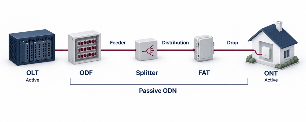
OLT optical interface → patching/ODF → feeder cable → splitter location(s) and distribution cabling → fibre access terminal (FAT) → drop cable → optional outlet and patch cord → ONT optical interface
This is an illustrative path, not a mandatory physical sequence. A closure is an enclosure, a splitter is an optical component, and a FAT may or may not contain a splitter. Show actual locations in the drawing. The OLT and ONT are active endpoints and are outside the passive-material scope unless separately requested.
The actual arrangement may use centralized splitting, cascaded splitting or a combination of both. The RFQ should identify:
- PON technology and equipment optical class: GPON, XGS-PON or another specified system; identify coexistence or upgrade requirements separately
- Total homes passed, homes connected and planned take-up
- Number of OLT/PON ports included in the project
- Split ratio, stages and installed quantity at each stage, such as a single 1×32 or a 1×4 stage feeding four 1×8 splitters
- Shortest and longest optical paths, differential reach where relevant, and permitted minimum/maximum path loss
- Aerial, duct, direct-buried, façade, indoor or mixed installation
- Central office, cabinet, handhole, pole and building termination points
- Current capacity, spare fibres and future expansion requirement
- Scope boundary: supply only, pre-assembly, installation or testing
GPON physical-layer requirements are defined in ITU-T G.984.2, while XGS-PON is covered by ITU-T G.9807.1. Record the applicable editions and amendments in the project specification. Naming the system alone does not define permitted optical loss.
Check the optical budget and coexistence boundary
Calculate relevant upstream and downstream paths using wavelength-appropriate cable attenuation and specified splitter, splice, mated-connector and other passive-device losses. State measurement reference planes so connector loss is neither omitted nor counted twice. Reserve an explicit engineering margin under the operator's design rules.
Check both maximum permitted loss and minimum path-loss/receiver-overload requirements. The shortest, lowest-loss branch also needs review. Meeting a loss limit alone does not establish compliant reach or subscriber capacity; the selected OLT/ONT combination and service design must support the proposed topology.
For multiple PON generations sharing an ODN, specify the coexistence arrangement and who supplies any external coexistence element, WDM/filter module and patching. Include wavelength-dependent insertion loss and isolation requirements. An integrated multi-PON module does not automatically require a separate external coexistence module. ITU-T G.9805 describes multiple coexistence approaches.
Quantity example: A fully populated 1×4 stage followed by one 1×8 splitter on each of its four outputs provides 32 output ports and requires five splitters: one 1×4 plus four 1×8 units. One 1×4 and one 1×8 unit do not populate all four branches. Two-stage path loss is the sum of the relevant two splitter losses plus interconnections; it need not equal the loss of a single 1×32 device. Output-port count is not a guarantee of service capacity.
1. Feeder cable
The feeder section carries traffic from the central office or hub toward the first distribution or splitting point. Its fibre count and route design affect both initial capacity and later expansion.
Specify:
- Route ID and installation method
- Cable construction: duct, aerial, direct buried, armoured or other project-specific design
- Fibre count and required spare-fibre policy
- Fibre category, such as ITU-T G.652.D or G.657.A1 where applicable
- Loose-tube, ribbon or other fibre organization
- Metallic or all-dielectric construction
- Water-blocking method
- Outer sheath material and required flame, UV, termite, rodent or chemical resistance
- Installation and long-term tensile limits, crush limits, installation/operating bend radii and temperature ranges, with test methods and units
- Drum length, length tolerance and drum schedule
- Cable marking, metre marking and project identification
- Applicable cable product/test standards, editions, test conditions, acceptance limits and required reports
Do not write only “144-core outdoor cable.” The same fibre count can describe substantially different products for duct, aerial and direct-buried routes.
Example description — complete it with project-specific limits before issue:
Feeder cable, 144F single-mode, G.652.D, all-dielectric loose-tube construction, duct installation, non-metallic strength members, water-blocked core, black UV-resistant PE sheath, sequential metre marking, supplied on route-specific drums with factory attenuation report. Attach cable diameter/tolerance, attenuation limits and test wavelengths, tensile/crush limits, installation/operating bend radii, temperature ranges and the drum schedule.
2. Distribution cable
Distribution cable connects a feeder or primary splitting point to neighbourhood, street, pole or building access points. It is often ordered by fibre count alone, even though branch layout and closure compatibility are equally important.
Specify:
- Route segment and destination
- Fibre count for each branch
- Fibre category and compatibility with the feeder and drop sections
- Cable diameter and construction
- Installation method and environmental exposure
- Mid-span access requirement, if any
- Tube count, fibres per tube and colour code
- Maximum pulling tension and separate installation/operating bend radii; for blown cable, specify the cable/microduct combination and installation conditions
- Closure entry compatibility and sealing range
- Drum or coil length for each route
- Required slack allocation and storage method
- Identification and test documentation
Where frequent branching is expected, confirm whether the selected cable structure supports the intended mid-span access method. This is a cable-and-closure decision, not a cable-only decision.
3. Drop cable
Drop cable is the final subscriber connection and usually has the highest unit count in the ODN. Small omissions are multiplied across hundreds or thousands of installations.
Specify:
- Indoor, outdoor, indoor/outdoor, aerial or duct application
- Fibre count, normally stated per subscriber connection
- Exact fibre subcategory, such as G.657.A1 or G.657.A2, and applicable edition; do not specify only “G.657”
- Flat, round, figure-8, self-supporting or other construction
- Strength member material
- Sheath material, colour and fire-performance requirement
- Cable dimensions and compatible clamp or entry-seal range
- Pre-terminated or field-terminated design
- Connector type and polish, such as SC/APC
- End A/end B configuration and connector protection
- Standard lengths, custom lengths and length tolerance
- Pulling eye or deployment reel requirement
- For connectorized assemblies: maximum insertion loss and minimum return loss, with wavelengths and reference connections; for unterminated cable: applicable cable attenuation requirements
ITU-T G.657 category A fibres are compliant with G.652.D; category B fibres are not necessarily compliant with all G.652.D attributes, although they are system-compatible in the stated access-network applications. The fibre's bending specification does not replace the finished cable's installation bend-radius limit. See ITU-T G.657.
Specify required fire-performance tests/classification for the installation location; a jacket material label alone does not define acceptance.
If pre-terminated drops are required, define the complete assembly. “SC/APC drop cable” does not explain whether one end or both ends are terminated, whether the far end is bare, or whether a hardened outdoor connector is required.
4. PLC splitters
The splitter affects optical loss, port utilization and the physical design of the closure, cabinet or ODF that houses it.
Specify:
- Input/output configuration: 1×N, or 2×N for an explicitly defined architecture; two inputs alone do not establish a protected PON
- Split ratio and number of splitting stages
- Equal-split ratio; if unequal taps are required, provide a per-port power allocation and loss schedule and request a suitable device separately
- Package type: bare fibre, blockless, mini-module, ABS box, cassette, rack-mount or tray
- Connectorized or unconnectorized inputs and outputs
- Connector type and polish on every port
- Pigtail fibre type, diameter and length
- Operating wavelength range
- Maximum insertion loss and maximum port-to-port loss uniformity; minimum return loss, with wavelengths, temperature range and test conditions
- Minimum directivity and maximum polarization-dependent loss (PDL), with applicable test conditions
- Operating temperature and environmental category
- Port numbering and label format
- Individual serial number and test report requirement
- Mounting compatibility with the selected closure, FAT, cabinet or ODF
Do not compare splitter prices until the package, connectorization, pigtail length and test criteria are aligned. A bare splitter and a connectorized cassette are not equivalent quotation items. State whether guaranteed insertion loss includes connector interfaces and identify the reference planes.
Return loss is normally specified as a positive dB minimum: larger values mean less returned power. Reflectance uses the opposite sign convention. For an illustrative requirement, RL ≥ 55 dB corresponds to reflectance ≤ −55 dB for the same measurement; 55 dB is not a universal acceptance limit. See IEC 61300-3-6 and the Corning parameter definitions.
Use the supplier's guaranteed maximum insertion loss for the ordered configuration, rather than a typical value or ideal splitting loss alone.
5. Closures, FATs and terminal boxes
The enclosure must fit the cable, splice, splitter and maintenance method—not merely the requested fibre count.
Specify:
- Function: straight joint, branch joint, splitter closure, fibre access terminal or customer terminal box
- Installation: pole, wall, strand, handhole, manhole or direct buried
- Dome or inline form factor
- Maximum splice capacity for the specified fibre/splice format and initial tray configuration; confirm capacity with splitters and storage installed
- Number of cable ports, branch ports and drop ports
- Cable diameter range for every port type
- Mechanical seal or heat-shrink seal
- Mid-span or uncut-cable access requirement
- Splitter type, quantity and mounting position
- Adapter interface, quantity and compatibility with the specified connector type/polish
- Pigtails included or excluded
- Fibre storage capacity and bend-radius control
- Ingress-protection and impact requirements, including cable-loaded configuration, sealed unused ports and immersion depth/duration where applicable
- UV, corrosion and temperature requirements
- Locking, grounding and pressure-test requirements, where applicable
- Pole/wall/strand mounting kit included or quoted separately
- Consumables and re-entry kit requirements
The general IEC 61300 framework covers test and measurement procedures for interconnecting devices, passive components, fibre-management systems and protective housings. The RFQ should still state the exact project specification, test severity and acceptance limit rather than writing only “IEC compliant.” See IEC 61300-1. A relevant product performance standard may also be needed; for example, IEC 61753-111-07 addresses sealed closures for aerial environments. Select the standard/category for the actual location. An IP rating alone does not demonstrate every mechanical, environmental or re-entry requirement.
Critical compatibility check: Match every cable outside diameter to the closure’s cable-entry sealing range. A closure may have enough splice capacity but still be unsuitable for the cable entering it.
6. ODFs and fibre patch panels
An ODF quotation may refer to an empty frame, a partially loaded frame or a fully loaded assembly. Define the loading condition clearly.
Specify:
- Rack, wall-mount or cabinet installation
- Rack width and height, such as 19-inch and required rack units
- Total fibre capacity and initial loaded capacity
- Fixed, sliding, swing-out or modular construction
- Adapter interface, connector-polish compatibility and quantity
- Simplex, duplex or quad adapter format
- Pigtail fibre type, connector and length
- Splice tray quantity and splice capacity
- Cable-entry direction and cable-fixing method
- Internal fibre-routing and bend-radius management
- Front patch-cord routing and label system
- Earthing requirement for metallic cable elements
- Housing material, finish and colour
- Accessories included: sleeves, cable glands, ties, labels and mounting hardware
- Factory assembly and testing requirement
Match connector type and polish at each mating point. Different interfaces can be used at different network positions with a correctly specified hybrid patch cord. An SC/APC-to-LC/UPC patch cord can be appropriate when each end mates to its matching interface; do not directly mate an APC end face to a UPC end face.
Specify adapter mechanical/keying compatibility; optical polish belongs to the connector ferrule, not the adapter sleeve. IEC 61754-4 defines SC-family interface dimensions, rather than a complete installed-link performance specification.
7. Patch cords, pigtails and adapters
These items complete the optical path but are frequently buried under a general “accessories” line. Apply the cable and end-connector fields below to patch cords, pigtails and terminated assemblies as appropriate; specify adapters separately by their mating interface and qualification requirements.
Specify:
- Product type: patch cord, pigtail, adapter or hardened connector assembly
- Connector at end A and end B
- Polish at both ends
- Simplex or duplex construction
- Fibre category
- Cable diameter and jacket material
- Length and tolerance
- Boot type and bend-relief requirement
- Colour and label format
- For terminated fibre products: maximum insertion loss, minimum return loss, test wavelengths and reference-connector conditions
- Routine optical test coverage/reporting for terminated assemblies; adapter dimensional, mating and qualification requirements, with an agreed sampling plan where appropriate
- Dust caps, pulling protection and individual packaging
Separate patch cords from pigtails in the material list. Also distinguish fibre paths, adapter bodies and cable assemblies: one duplex patch cord contains two fibre paths but is one assembly. A passive adapter is assessed with appropriate mating connectors; do not request a standalone adapter return-loss value as though it were a terminated fibre assembly.
8. Installation and protection accessories
Accessories should be derived from the installation method and cable dimensions. They should not be added as a generic percentage of the cable value.
Depending on the design, the RFQ may include:
- ADSS suspension and tension assemblies selected for cable construction/diameter, span, mechanical loads and installation conditions
- Pole bands, brackets, hooks and stainless-steel straps
- Aerial drop clamps and anchoring hardware
- Duct plugs, cable seals and microduct connectors
- Pulling eyes, swivels, rollers and cable lubricants
- Cable glands and entry grommets
- Splice-protection sleeves
- Fibre-management rings, guides and storage baskets
- Slack-storage brackets
- Warning tape, marker posts and route labels
- Grounding kits for metallic elements
- Wall plugs, screws and mounting kits
- Cleaning tools and connector inspection consumables
- Spare seals and closure re-entry kits
For every hardware item, state the compatible cable diameter, load or mounting surface. “Drop clamp, 2,000 pcs” is incomplete unless the supplier knows the drop-cable dimensions and whether the clamp will be installed on poles, façades or messenger wire.
Build the quantities from network positions
A reliable quantity schedule should trace each item to a drawing, route or service point.
| Item | Recommended quantity basis | Common omission |
|---|---|---|
| Feeder cable | Route length by segment, plus defined slack and contingency | Drum plan and route-specific lengths |
| Distribution cable | Branch-route length and fibre count | Mid-span access and closure entry size |
| Drop cable | Connected premises or installation forecast by standard length | One-end/two-end termination definition |
| Splitter | PON topology, usable ports and planned spare capacity | Package and mounting format |
| Closure/FAT | Joint, branch, splitter and service-point locations | Trays, adapters, mounting and sealing kits |
| ODF | Cable terminations, PON ports and expansion reserve | Empty versus fully loaded configuration |
| Patch products | Actual optical interfaces at both ends | Connector polish and simplex/duplex counting |
| Accessories | Installation method, cable diameter and mounting point | Compatibility and replacement consumables |
Do not hide spare quantities inside an unexplained total. Show the installed quantity, commissioning spare and maintenance spare separately so that all bidders quote the same scope.
Cross-check the interfaces before sending the RFQ
The most expensive ODN errors are often interface errors between individually acceptable products.
Check that:
- Fibre categories are compatible across feeder, distribution, drop and pigtails
- Connector type and polish match at every mating point
- Splitter package fits the intended tray, cassette, closure or cabinet
- Cable diameter fits every gland, seal, clamp and closure port
- Closure tray capacity matches the splice plan, not only the cable fibre count
- ODF fibre-port capacity, loaded adapters, pigtails and patch cords reconcile with the termination/patching plan; their quantities need not be equal
- Cable construction matches the pulling, aerial loading or burial method
- Applicable metallic elements have a defined bonding/grounding approach under the project design and local requirements
- Labels use one naming system across cables, splitters, ports and drawings
- The optical budget covers the relevant wavelengths, mated connector pairs, splices, splitter stages, any coexistence devices and the agreed margin
Define testing and acceptance deliverables
Separate qualification/type-test evidence, routine production tests and installed-network acceptance. Environmental qualification is not automatically a test on every shipped item. A factory component report is not an installed-link acceptance report.
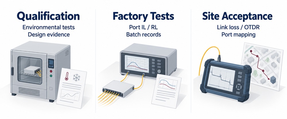
Product names alone do not define what evidence the buyer will receive.
State which of the following are required:
- Cable attenuation test by fibre and wavelength
- Splitter insertion-loss test by output port
- Patch cord and pigtail insertion-loss and return-loss results
- Connector end-face inspection criteria
- Closure sealing or environmental test evidence
- Material and compliance certificates
- Factory inspection or pre-shipment inspection
- Drum, closure and splitter serial-number traceability
- Packing list linked to route, segment or site ID
- Planned label schedule and port map with the supply package; as-built records after installation by the responsible party
- Installation manuals and datasheets
- Warranty terms and non-conformance procedure
Identify test method, wavelength, reference plane, acceptance limit, sampling/coverage, report format and responsible party. Relevant component methods include IEC 61300-3-4 for attenuation, IEC 61300-3-6 for return loss and IEC 61300-3-35 for connector end-face inspection. Visual inspection does not replace optical performance measurement.
If installation/commissioning is included, add an operator-approved field plan: end-to-end loss measurement, OTDR event/trace records where required, continuity and port mapping, and wavelength-selective PON power measurements at activation where applicable. Define OTDR direction(s), launch/receive leads, splitter measurement capability and live-network restrictions. For splice-loss assessment, specify bidirectional averaging where needed to address backscatter mismatch. OTDR traces and end-to-end loss measurements serve different purposes.
Assign field testing explicitly if the order is supply-only. EXFO's PON testing reference distinguishes deployment, activation and troubleshooting measurements.
ODN RFQ review checklist
Use this review list to assemble the inquiry package. Complete project-specific values, drawings, quantities and the acceptance schedule before issue; checked boxes alone are not a technical specification.
A. Project and topology
B. Feeder cable
C. Distribution cable
D. Drop cable
E. PLC splitters
F. Closures, FATs and terminal boxes
G. ODFs and patch panels
H. Patch cords, pigtails and adapters
Apply end, fibre and jacket fields to fibre assemblies; list adapter interface, quantity and mating/qualification requirements separately.
I. Installation accessories
J. Commercial and delivery information
Common RFQ mistakes to avoid
- Quoting cable by fibre count only. Installation method, construction and environment can change the product completely.
- Specifying the split ratio but not the splitter package. A bare splitter, ABS module and cassette require different housings and labour.
- Ordering closures by splice capacity only. Port count, cable diameter, sealing and splitter space may become the real limits.
- Requesting an ODF without defining whether it is loaded. Adapter, pigtail, tray and sleeve scope must be visible.
- Directly mating APC and UPC end faces. Specify compatible interfaces at each connection; a correctly selected hybrid patch cord can connect different interface types at opposite ends.
- Combining patch cords, pigtails and adapters under one accessory line. They have different quantities and acceptance criteria.
- Using one percentage for all installation hardware. Hardware must follow cable diameter, route and mounting method.
- Leaving testing until after the purchase order. Acceptance evidence should be agreed in the RFQ.
From a product list to an installable ODN package
The goal of an ODN RFQ is not to collect the lowest unit prices for eight unrelated product groups. It is to receive a coordinated package in which the cables, splitters, enclosures, termination hardware and accessories fit the same topology and acceptance plan.
Preparing an ODN material inquiry for ZION? Send the network drawing, route schedule, splitter layout, interface requirements, quantities and delivery destination. Request an itemized quotation showing proposed products, included accessories, available test documentation, exclusions and technical deviations. State separately any design-review, installation or commissioning services required.
Reference links
- ITU-T G.984.2 — GPON physical media dependent layer
- ITU-T G.9807.1 — XGS-PON
- ITU-T G.657 — Bending-loss insensitive single-mode fibre and cable
- IEC 61300-1 — General test and measurement guidance, consolidated version including 2025 amendment
- IEC 61754-4 — SC connector family interface standard and related editions
Prepare your ODN inquiry
Submit the network drawing, route schedule, splitter layout, connector requirements, quantities and delivery destination. Include the required test documents and any installation or commissioning scope.
Request Project Support


