
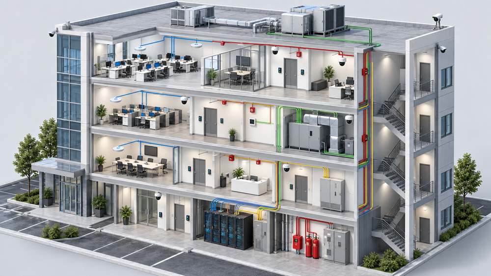
A smart building is not purchased as one product. It is assembled from several systems that share pathways, telecom rooms, backbone links and project documentation while performing very different functions.
That is why a useful smart building bill of materials cannot be a generic shopping list. It must translate the approved design into a coordinated project BOM covering:
- fire alarm;
- access control;
- building management systems;
- ICT and structured cabling;
- CCTV and security networks;
- fiber-optic backbone infrastructure;
- shared racks, pathways, power, grounding, labeling and test records.
In practice, “smart building BOM” can mean either a complete system BOM or a cabling-and-connectivity BOM. This guide focuses on the second. Active equipment—such as fire alarm control panels, controllers, switches, cameras, servers and software—is included only where it defines a cable, interface, power or termination requirement. A full system BOM must add the approved equipment models, licenses, power supplies, batteries, software, commissioning services and manufacturer-specific accessories.
This guide shows how consultants, contractors and buyers can build a coordinated cabling-and-connectivity BOM without mixing incompatible systems or overlooking the small components that often delay installation.
Important: The examples below are planning references, not a final engineered design. The adopted electrical, fire, life-safety, building and telecommunications requirements—and the approved project specification—take priority. The authority having jurisdiction (AHJ) determines which codes and editions apply.
What Is a Smart Building Project BOM?
A smart building cabling BOM is a structured list of the cables, connectivity products, enclosures and installation accessories required to connect the building's ELV, control and communication systems.
The terms BOM and BOQ are often used loosely, but they are not identical. A BOM defines the items and assemblies required to build the system. A bill of quantities (BOQ) records measured quantities for tendering, pricing or payment. On a project, the approved design and measurement rules should state which document controls.
It should answer four questions:
- What must be connected? Every outlet, camera, door, detector, controller, sensor and equipment panel needs to be identified.
- How is it connected? The topology determines whether a link uses Ethernet, fiber, RS-485, KNX, fire-alarm circuit cable or another medium.
- Where does it terminate? A cable without its panel, module, connector, cabinet or splice accessory is not a complete BOM line.
- How much is required? Quantities must be derived from routes, device counts, floor layouts, redundancy and installation allowance—not only from the number of endpoints.
The related Smart Building Network Topology guide should be completed before the final BOM. The topology establishes the physical and logical connections; the BOM converts those connections into purchasable line items.
Information Required Before Building the BOM
Do not begin with product models. Begin with the project inputs.
Building information
- building type and occupancy;
- number of buildings, floors and telecom rooms;
- main equipment room or MDF location;
- floor distributor or IDF locations;
- riser, ceiling, tray, conduit and outdoor routes;
- environmental conditions and installation method;
- required fire reaction, smoke, halogen and circuit-integrity performance.
System point schedules
- ICT outlets, wireless access points and IP phones;
- fixed, dome, bullet, panoramic and PTZ cameras;
- controlled doors, readers, locks, contacts and exit devices;
- fire alarm loops, zones, detectors, manual call points, sounders and interfaces;
- BMS controllers, sensors, actuators, meters and field-bus segments;
- fiber links, active fiber requirements and resilience paths.
Commercial and compliance information
- approved standards and local code;
- copper category, shielding and PoE requirements;
- fiber type, fiber count and connector interface;
- the required jurisdiction-specific cable classification—for example, an EU reaction-to-fire class, a North American plenum/riser listing, or an LSZH requirement;
- required certifications, test reports and submittals;
- drum or box length, packaging, labeling and delivery phases.
These terms are not interchangeable. A CPR reaction-to-fire class, a plenum or riser listing, an LSZH construction and a circuit-integrity rating address different requirements. Record the applicable standard and classification rather than combining them into a generic phrase such as “LSZH fire-rated cable.”
If these inputs are missing, the first deliverable should be an assumptions register rather than a final quotation.
Master Smart Building BOM Structure
| System | Typical endpoints | Common cable families | Termination and infrastructure | Main quantity driver |
|---|---|---|---|---|
| Fire alarm | Detectors, call points, sounders, modules | Fire alarm cable, fire-resistant control cable | Fire alarm control panel (FACP), loop modules, terminals, junction boxes | Loops, zones, device schedule and approved circuit design |
| Access control | Readers, locks, contacts, exit buttons | Access-control composite cable, security cable, Cat6 | Door controllers, power supplies, enclosures | Controlled doors and reader configuration |
| BMS | Sensors, actuators, meters, DDCs | RS-485, KNX, control cable, Cat6/Cat6A | Controllers, gateways, field panels | Point list, controller layout and bus segments |
| ICT | Work-area outlets, APs, phones, printers | Cat6/Cat6A, fiber, patch cords | Patch panels, keystones, faceplates, racks | Outlet count, PoE devices and floor distribution |
| CCTV | IP cameras, intercoms, security workstations | Cat6/Cat6A, fiber, power/control cable | PoE switches, NVR/VMS, patch panels | Camera count, bandwidth, distance and PoE load |
| Fiber backbone | MDF, IDFs, remote buildings and cabinets | Indoor, riser, indoor/outdoor or outdoor fiber cable | ODFs, panels, pigtails, adapters and splice protection | Backbone links, fiber count, route diversity and growth |
| Shared infrastructure | All systems | Grounding/earthing conductors and pathway segregation products | Racks, cabinets, PDU, tray, labels and management | Rooms, racks, routes and project handover requirements |
The BOM should preserve these system boundaries even when several systems use the same pathways or Ethernet infrastructure.
1. Fire Alarm BOM
The fire alarm package must follow the approved fire strategy, cause-and-effect matrix, authority requirements and panel manufacturer's design rules. It should not be treated as an ordinary data network.
Typical cabling BOM sections include:
- control-panel and repeater-panel interfaces, plus the active equipment itself when it is within the package scope;
- addressable loop or conventional circuit cable;
- power and notification circuit cable where applicable;
- detectors, bases, manual call points, sounders and visual alarm devices;
- input/output and isolation modules;
- junction boxes, glands, terminals, supports and fixings with the required listing or project approval;
- interfaces to lifts, HVAC shutdown, smoke control, access release and monitoring systems;
- end-of-line components where required;
- labels, test sheets and commissioning documentation.
Cable descriptions must separate reaction-to-fire performance from circuit integrity. LSZH describes smoke and halogen behavior; it does not mean that a cable will maintain circuit operation during a fire. The IEC 60331 series contains cable test methods for circuit integrity under specified fire conditions; the applicable part depends on cable construction and diameter. For example, IEC 60331-2:2018 covers certain cables up to 20 mm overall diameter under fire with mechanical shock at a temperature of at least 830°C.
Do not specify a fire-survival duration or construction from a marketing name alone. Record the precise standard and part, test condition, duration, voltage rating and project approval requirement. A cable test result also does not prove that the complete installed circuit will survive: supports, fixings, joints, penetrations and installation method must comply with the project’s adopted system requirements.
2. Access Control BOM
One controlled door can require several different conductors. Counting only the reader cable is a common BOQ error.
For each door, confirm:
- number and type of readers;
- electric strike, maglock or other locking device;
- request-to-exit button or sensor;
- door contact;
- emergency break-glass unit where specified;
- local power supply and battery backup;
- controller location and network connection;
- fire-alarm interface and supervised release requirements, where required by the approved life-safety and egress design.
The cable package may use individual reader, lock, contact and request-to-exit cables, or an approved composite access-control cable. IP readers and door controllers may also require balanced copper cabling, but the lock, egress and safety circuits still need their specified conductors and power arrangement. Do not assume that every door must unlock through the same generic fire-alarm interface; the sequence must follow the approved code, egress strategy, hardware listing and cause-and-effect design.
Build the BOM per door type rather than multiplying one universal door kit across the project. A single-reader office door, a two-reader anti-passback door, a vehicle gate and an emergency exit have different requirements.
3. BMS BOM
The BMS BOM should start from the controls point schedule and network architecture. Equipment names alone are not enough.
Typical components include:
- BMS server, workstation or supervisory controller;
- DDCs, programmable controllers and remote I/O modules;
- BACnet/IP, BACnet MS/TP, Modbus, KNX or vendor-specific gateways;
- temperature, humidity, pressure, air-quality and occupancy sensors;
- actuators, valves, dampers, relays and transducers;
- energy, water and thermal meters;
- RS-485, KNX, control, instrumentation and Ethernet cable;
- control panels, terminals, power supplies and network accessories;
- end-of-line termination and shield-grounding provisions where required.
ANSI/ASHRAE Standard 135-2024 defines BACnet data communication services and protocols for building automation and control networks and is maintained through published addenda and errata. The protocol name alone does not define the cable: BACnet/IP over Ethernet and BACnet MS/TP over an RS-485 physical layer use different infrastructure. The BOM must name the BACnet data link or physical layer, not simply state “BACnet cable.”
For every BMS line, state:
- protocol and physical layer;
- conductor count and size;
- characteristic impedance where applicable;
- shielding requirement;
- maximum segment length and device loading from the approved design;
- topology and termination method;
- indoor, outdoor, riser or fire-performance requirement.
4. ICT and Structured Cabling BOM
The ICT package normally establishes the structured cabling platform used by computers, phones, wireless access points and many IP-based building devices.
The BOM can include:
- Cat6 or Cat6A horizontal cable, plus single-pair balanced cabling only where the approved application and device ecosystem require it;
- shielded or unshielded patch panels;
- keystone jacks, faceplates and back boxes;
- work-area and equipment patch cords;
- floor racks or wall-mount cabinets;
- horizontal and vertical cable management;
- PoE and non-PoE switches;
- PDU, UPS interfaces and rack accessories;
- grounding and bonding components;
- labels and certification test records.
ISO/IEC 11801-1:2017, including its published corrigendum and 2025 amendment, defines general requirements for multi-vendor generic cabling that supports services including voice, data, video and power delivery. ANSI/TIA-862-C, released in 2022, addresses cabling topology, architecture, design, installation, testing and components for intelligent building systems, particularly systems that use or can use IP-based infrastructure.
The cable category is only one part of the decision. Buyers should also confirm the application, permanent-link and channel configuration, remote-power load, bundle size, ambient temperature, shielding and bonding, jurisdiction-specific fire classification, installation stress and acceptance test limit. Patch cords, connectors and installation workmanship must support the specified channel performance; a higher category marking on the cable alone does not guarantee it.
5. CCTV BOM
For IP surveillance systems, the BOM varies considerably by camera location, environmental conditions and network design.
Typical line items include:
- indoor and outdoor IP cameras;
- Cat6 or Cat6A horizontal cable;
- outdoor, UV-resistant or armored cable where required;
- PoE switches and optical uplinks;
- fiber cable and media interfaces for remote buildings or long routes;
- patch panels, patch cords and equipment cabinets;
- NVR, VMS server, storage and monitoring equipment;
- surge protection, grounding and weatherproof boxes;
- poles, brackets, glands and installation accessories.
Calculate switch quantities from more than port count. The design must also consider total PoE budget, per-port power requirement and negotiation, uplink capacity, environmental rating, redundancy and spare capacity. Size recording storage separately from camera count using the approved resolution, frame rate, codec, scene activity or recording mode, target bitrate, retention period, storage overhead and redundancy scheme.
If a camera route exceeds the approved balanced-copper channel design, do not solve the problem by simply purchasing a longer Cat6 cable. Reposition the switch, add a properly designed intermediate distribution point, or use fiber and local power as required.
6. Fiber Backbone BOM
Fiber commonly connects the main distribution frame (MDF), intermediate distribution frames (IDFs), security rooms, plant areas, remote cabinets and separate buildings where distance, bandwidth or electromagnetic conditions make balanced copper unsuitable. Fiber is immune to electromagnetic interference in the transmission medium, but its reach is still limited by the optical link budget, transceivers, connectors, splices and application standard.

The fiber BOM should include:
- fiber type selected for the application, transceiver, wavelength and reach—for example, OS2, OM3 or OM4;
- cable construction: riser, LSZH, indoor/outdoor, duct, armored or other approved type;
- fiber count per link;
- primary route and diverse-route quantities where resilience is required;
- rack-mount or wall-mount fiber panels;
- pigtails, adapters, splice trays and sleeves, including connector type and polish where relevant;
- equipment patch cords;
- glands, breakout kits and cable-management products;
- closures or outdoor distribution boxes where applicable;
- cleaning, inspection and test requirements.
Fiber count should not be based only on today's transceivers. Record active fibers, resilience requirements, reserved fibers and realistic growth separately. Do not call two fibers “redundant” if they share the same cable and route: route diversity, cable diversity and equipment redundancy are different design decisions.
Shared Infrastructure: The Part Most Often Missed
A coordinated BOM needs a common-infrastructure section. Otherwise, each subcontractor may assume another package is supplying the same item.
Check the responsibility for:
- MDF and IDF racks or cabinets;
- cable tray, basket, ladder, conduit and sleeves;
- fire stopping at penetrations;
- PDU, UPS and dedicated power outlets;
- grounding and bonding;
- environmental monitoring and cabinet ventilation;
- fiber and copper cable management;
- equipment mounting hardware;
- labels, identifiers and as-built documentation;
- test equipment, test limits and acceptance reports;
- spare cables, modules, patch cords and repair materials.
The BOM should show whether these items are included, by others or to be confirmed. Leaving the cell blank transfers uncertainty into the installation phase.
How to Calculate Cable and Connectivity Quantities
Horizontal copper cable
A more auditable planning method is:
Design cable length = measured pathway length + vertical drops + defined service loops + termination allowances
Purchase quantity = design cable length + documented cutting/waste allowance, rounded through a reel or box plan
Keep each allowance visible. A single multiplier hides whether additional cable is intended for routing uncertainty, service loops, termination, packaging or waste, and it can conflict with the later purchasing calculation.
Do not multiply the longest route by every point. Use measured or grouped average routes by floor, zone or telecom room.
Copper connectivity
For each balanced-cabling outlet or device link, identify the architecture first:
- a permanent link normally includes the fixed horizontal cable and its terminations, but not equipment or work-area patch cords;
- a channel includes the permanent-link components plus the applicable cords and connections;
- a modular plug terminated link (MPTL) or direct-attach arrangement has a different connector and acceptance-test configuration.
For the BOM, count patch-panel ports, outlets or device plugs, consolidation points where used, equipment cords, work-area/device cords, labels and the correct certification-test scope separately. Do not describe every IP-device run as a permanent link.
Fiber backbone
For every backbone link, calculate:
- installed cable length from the approved route;
- service loop and termination allowance;
- fiber count and cable quantity;
- panel capacity at both ends;
- pigtail and splice quantities when fusion splicing is used;
- adapter and patch-cord quantities;
- redundant route and spare capacity;
- optical loss test set (OLTS) acceptance testing and optical time-domain reflectometer (OTDR) testing where required by the specification.
Specify test wavelengths, reference method, direction, test-cord configuration, link type and acceptance limits. An OTDR trace is useful for event characterization and troubleshooting, but it is not an automatic substitute for insertion-loss acceptance testing. ISO/IEC 14763-3:2024 covers testing of installed optical-fiber cabling.
Access control
Create repeatable door types, such as:
- D1: single reader and electric strike;
- D2: entry and exit readers with maglock;
- D3: emergency exit with monitored release;
- D4: vehicle gate with long outdoor route.
Multiply each approved door-type BOM by its door schedule quantity, then add central controllers, cabinets and network links.
BMS
Group quantities by controller panel and field-bus segment. Count cable routes from the controller to field devices according to the actual daisy-chain, trunk-and-spur or home-run design. Do not multiply the controller-to-device distance as if every sensor were a home run when the approved topology uses a bus.
Recommended BOM Columns
Use a procurement table that can move from design review to RFQ and order without losing technical context.
| Field | Purpose |
|---|---|
| System | Fire, access, BMS, ICT, CCTV, fiber or shared infrastructure |
| Item code | Project or customer reference |
| Product description | Clear, non-brand-specific description |
| Technical specification | Construction, conductor/fiber, rating, protocol and performance |
| Standard/compliance | Required standard, test or approval |
| Unit | Meter, piece, set, box, drum or lot |
| Design quantity | Quantity calculated from the design |
| Installation allowance | Separately stated additional quantity |
| Purchase quantity | Rounded quantity based on packaging or drum length |
| Location/zone | Building, floor, room or route |
| Approved equivalent | Alternate construction or model rules |
| Supplier remarks | Deviation, document and lead-time notes |
Keeping design quantity, allowance and purchase quantity separate makes the BOM auditable.
From BOM to RFQ: Information the Supplier Needs
An RFQ should state more than product name and total meters.
For cable lines, include:
- application and system;
- conductor or fiber construction;
- pair/core/fiber count;
- conductor size or fiber grade;
- shielding and armor;
- voltage and temperature rating where applicable;
- jacket material, color and marking;
- fire, smoke and halogen performance;
- standard and certificate requirements;
- packaging length and quantity;
- destination, trade term and required delivery date.
For connectivity products, include interface, port count, rack unit, mounting format, adapter or connector type, loaded/unloaded requirement and included accessories.
Common Smart Building BOM Mistakes
Treating every system as Ethernet
CCTV and ICT are commonly IP-based, but BMS field buses, door circuits and fire alarm loops may use different media and topology.
Specifying “LSZH fire-resistant cable” without a test standard
LSZH and circuit integrity describe different properties. The specification must state the required fire test and acceptance criteria.
Counting devices but not routes
Two projects with the same number of cameras can require very different cable quantities because of floor area, IDF placement and outdoor routes.
Omitting termination and accessories
Cable without panels, pigtails, modules, glands, splice protection and patch cords is not installable.
Hiding all spare capacity inside one percentage
Separate installation allowance, service loops, redundant links, reserved ports and future expansion. They address different risks.
Ignoring packaging and installation sequence
The calculated meter quantity must be converted into practical boxes, reels or drums without creating unnecessary joints or waste.
Smart Building BOM Checklist
Before releasing the BOM for quotation, confirm:
- Every system has an approved topology or schematic.
- Device and point schedules match the latest drawings.
- MDF, IDF, controller and panel locations are fixed.
- Cable routes and installation environments are identified.
- Copper application, category/class, link model, shielding and remote-power requirements are stated.
- Fiber type, fiber count and connector interface are stated.
- BMS protocols and physical layers are separated.
- Fire cable requirements cite the applicable test or code.
- Door types include reader, lock, contact and exit functions.
- Panels, modules, connectors and installation accessories are included.
- Racks, pathways, power, grounding and fire stopping have an owner.
- Design quantity and installation allowance are shown separately.
- Packaging lengths and staged delivery requirements are confirmed.
- Copper and fiber test configurations, limits, labels, submittals and as-built records are included.
- Deviations and approved equivalents are documented.
Conclusion
The purpose of a coordinated smart building BOM is to manage the interfaces, shared infrastructure and purchasing requirements of fire alarm, access control, BMS, ICT, CCTV and fiber without pretending that they are one technical system. Keep system-specific designs and approvals intact, then consolidate the purchasable items and responsibilities into a controlled project document.
A reliable workflow is:
Point Schedule → Network Topology → Cable Routes → Terminations → Quantity Calculation → Project BOM → RFQ
For a ZION project quotation, submit the BOQ, cable schedule, topology and relevant specifications. The response should identify the proposed products, standards, stated deviations, packaging and commercial terms so the project designer or approving authority can assess the offer against the approved design.
Frequently Asked Questions
Is a smart building BOM the same as an equipment list?
No. An equipment list identifies devices and panels. A complete system BOM also covers software, licenses, power supplies, batteries, manufacturer-specific accessories, and services. A cabling-and-connectivity BOM covers cables, terminations, racks, enclosures, patch cords, splice accessories, labels, pathways, and testing requirements.
Can CCTV, access control and BMS share the same fiber backbone?
They may use common pathways or a shared structured-cabling plant when the approved architecture, code, cybersecurity policy, capacity, and resilience requirements allow it. Sharing passive fiber differs from sharing active network equipment, and VLANs alone do not satisfy every availability, cybersecurity, or life-safety segregation requirement.
Should Cat6 or Cat6A be used throughout a smart building?
The selection depends on application speed, PoE load, channel length, environment, bundle conditions, shielding, and project standards. A single category should not be chosen only for marketing simplicity.
How much spare cable should be included?
There is no universal percentage for every project. Installation waste, service loops, packaging, spare ports, reserved fibers, and future growth should be calculated and recorded separately.
What should be sent to ZION for a project quotation?
Send the latest BOQ, system drawings or topology, cable schedule, relevant specifications, quantities, standards, packaging requirements, destination, and required delivery date. Mark any item that needs an approved alternative.
References
Standards status was checked on 18 September 2026. A project specification should cite the edition adopted by the contract and authority having jurisdiction; the newest published edition is not automatically the legally adopted edition.
- Telecommunications Industry Association, ANSI/TIA-862-C: Structured Cabling Infrastructure Standard for Intelligent Building Systems (released 2022).
- ISO, ISO/IEC 11801-1:2017 — Generic cabling for customer premises, Part 1, including Cor 1:2018 and Amd 1:2025 with its technical corrigendum.
- ASHRAE, ANSI/ASHRAE Standard 135-2024 — BACnet, with applicable published addenda and errata.
- KNX Association, KNX topology overview.
- NFPA, NFPA 72, 2025 edition — National Fire Alarm and Signaling Code, where adopted.
- IEC, IEC 60331-2:2018 — Circuit integrity under fire with mechanical shock for applicable cables up to 20 mm overall diameter. Use the applicable IEC 60331 part for the cable and test condition.
- ISO, ISO/IEC 14763-3:2024 — Testing of optical-fiber cabling.
- ISO, ISO/IEC 14763-4:2021 — Measurement of E2E links, MPTLs and direct-attach cabling.
Prepare a Clear Project BOM for Quotation
Submit the latest BOQ, system topology, cable schedule, applicable standards, quantities, packaging requirements, destination, and delivery window. The quotation can then identify proposed products, stated deviations, packaging, and commercial terms for project review.
Request Project Support


