What Is This 24 AWG F/UTP Cat 5e Cable?
This cable is designed for horizontal LAN cabling and other fixed Ethernet links operating from 1 to 100 MHz. Its four color-coded twisted pairs carry data, while the overall foil layer helps reduce external electromagnetic interference compared with an unshielded U/UTP construction.
The standard package is a 305 m pull box for efficient cable payout during installation. Conductor choices include bare copper (BC) and copper-clad aluminum (CCA), with commonly produced conductor diameters from 0.45 mm to 0.51 mm. PVC, LSZH and PE jacket materials are available for different indoor and outdoor requirements.
Cable Construction
Blue, orange, green and brown pair identification with HDPE-insulated conductors.
Aluminum/polyester foil surrounds the four pairs, with the foil face specified outward.
Typical F/UTP construction uses a 0.40 ± 0.005 mm tinned-copper drain wire.
PVC, LSZH or PE can be selected according to fire, smoke and environmental requirements.
Cat 5e Construction Variants
The available Cat 5e cable family includes U/UTP, F/UTP, SF/UTP and dual U/UTP constructions. Compare the conductor, shielding, drain wire and jacket dimensions below to select the appropriate version.
U/UTP Cat 5e Twisted Pair Installation Cable
| Item | Specification |
|---|---|
| Conductor | 24 AWG solid bare copper |
| Pairs | 4 pairs |
| Insulation | HDPE |
| Insulation colors | White/blue–blue, white/orange–orange, white/green–green, white/brown–brown |
| Rip cord | Cotton |
| Outer jacket | 5.1 ± 0.2 mm |

F/UTP Cat 5e Twisted Pair Installation Cable
| Item | Specification |
|---|---|
| Conductor | 24 AWG solid bare copper |
| Pairs | 4 pairs |
| Insulation | HDPE |
| Insulation colors | White/blue–blue, white/orange–orange, white/green–green, white/brown–brown |
| Rip cord | Cotton |
| Drain wire | 0.40 ± 0.005 mm tinned copper |
| Overall shield | Aluminum/polyester foil, foil face out |
| Outer jacket | 6.3 ± 0.2 mm |

SF/UTP Cat 5e Twisted Pair Installation Cable
| Item | Specification |
|---|---|
| Conductor | 24 AWG solid bare copper |
| Pairs | 4 pairs |
| Insulation | HDPE |
| Insulation colors | White/blue–blue, white/orange–orange, white/green–green, white/brown–brown |
| Rip cord | Cotton |
| Drain wire | 0.40 ± 0.005 mm tinned copper |
| Overall shield | Aluminum/polyester foil, foil face out, plus tinned-copper braid |
| Outer jacket | 6.5 ± 0.2 mm |

U/UTP Dual Cat 5e Twisted Pair Installation Cable
| Item | Specification |
|---|---|
| Conductor | 24 AWG solid bare copper |
| Pairs | 4 pairs per cable element |
| Insulation | HDPE |
| Insulation colors | White/blue–blue, white/orange–orange, white/green–green, white/brown–brown |
| Rip cord | Cotton |
| Outer jacket | (5.2 × 10.4) ± 0.2 mm |

Key Benefits
Suitable for standard Ethernet applications when the complete installed channel meets the specified test limits.
Foil shielding helps control external noise in offices, equipment rooms and light industrial cabling routes.
Select BC for lower resistance priorities or CCA where the project explicitly permits that construction.
Match PVC, LSZH or PE to the installation environment and applicable safety requirements.
A 305 m pull box and descending length markings help installers monitor remaining cable and reduce scrap.
Conductor size, insulation diameter, jacket color, printing, packaging and test requirements can be confirmed for the order.
Applications
The available Cat 5e constructions are designed around the following network and installation requirements:
- ANSI/TIA-568-C.2 Category 5e and ISO 11801 2nd Edition Class D channel requirements.
- ANSI/TIA-568-C.2 and IEC 61156-5 Category 5e component requirements.
- Third-party Category 5e channel compliance testing where specified for the order.
- IEEE 802.3af and IEEE 802.3at PoE applications when the selected conductor and complete channel meet the required electrical limits.
- Horizontal structured cabling for office, retail, education and commercial buildings.
- Switch-to-work-area links requiring Gigabit Ethernet capability within Cat 5e channel limits.
- IP cameras, access points, VoIP phones and other network devices where PoE requirements are confirmed against the selected cable build.
- Equipment rooms and light industrial routes where an overall foil shield can help manage electromagnetic interference.
- Indoor or protected outdoor installations using a jacket selected for the actual environmental and code requirements.
- Descending length markings for easier remaining-length identification and reduced installation scrap.
- Additional jacket colors for project identification and private-label programs.
Selection Guide: BC vs CCA and Jacket Options
| Decision | Recommended Direction | Confirm Before Ordering |
|---|---|---|
| Conductor material | Use solid bare copper when low DC resistance, PoE performance and formal channel compliance are priorities. Use CCA only where the project specification permits it. | BC or CCA, conductor diameter, maximum DC resistance and required test report. |
| Shielding and grounding | Use F/UTP with shielded jacks, patch panels and appropriate bonding when EMI control is needed. | Grounding method, shield continuity and compatible connecting hardware. |
| Indoor jacket | Choose PVC for general indoor use or LSZH where low smoke and halogen requirements apply. | Local fire code, flame rating, color and marking. |
| Outdoor exposure | Choose PE or another project-approved outdoor jacket for moisture and sunlight exposure. | UV, water, conduit, temperature and direct-burial requirements. |
| PoE loading | Prefer bare copper and evaluate bundle size, ambient temperature and current requirements. | IEEE power level, pair count, run length, bundling and installation temperature. |
Technical Specifications
| Parameter | Available or Typical Value |
|---|---|
| Cable category | Category 5e |
| Construction | F/UTP, 4 unshielded twisted pairs with overall foil shield |
| Conductor | Solid bare copper or copper-clad aluminum; 0.45, 0.48, 0.49, 0.50 or 0.51 mm commonly available |
| Nominal 24 AWG reference | 0.511 mm diameter; 0.205 mm² cross-sectional area |
| Pair insulation | HDPE; typical finished insulation diameter 0.88–1.00 mm |
| Pair colors | White/blue–blue, white/orange–orange, white/green–green, white/brown–brown |
| Overall shield | Aluminum/polyester foil, foil face out |
| Drain wire | 0.40 ± 0.005 mm tinned copper |
| Rip cord | Cotton |
| Outer jacket | PVC, LSZH or PE |
| Typical F/UTP outer diameter | 5.3, 5.6 or 6.0 mm production options; a 6.3 ± 0.2 mm version is also listed |
| Package length | 305 m pull box |
| Typical box size | 32 × 32 × 28 cm |
| Installation temperature | 0°C to +50°C |
| Operating temperature | -20°C to +75°C |
Factory common production dimensions
These production combinations were listed as common options capable of passing a 90 m Fluke test. Final performance still depends on the complete ordered construction.
| Construction Item | Available Dimensions |
|---|---|
| Conductor diameter | 0.45, 0.48, 0.49, 0.50, 0.51 or 0.52 mm |
| Insulation diameter | 0.88, 0.90, 0.92, 0.95 or 1.00 mm |
| U/UTP outer diameter | 5.0 mm |
| F/UTP outer diameter | 5.3, 5.6 or 6.0 mm |
| SF/UTP outer diameter | 6.2 or 6.4 mm |
| U/UTP dual | 5.0 × 11 mm |
| F/UTP dual | 5.6 × 12 mm |
| U/UTP self-supporting | 5.0 × 2.5 mm |
| F/UTP self-supporting | 5.6 × 2.5 mm |
Electrical and Channel Performance
The values below summarize the published Cat 5e construction. They should be confirmed against the exact conductor, cable diameter and test standard specified for the order.
| Parameter | Published Value | Unit / Condition |
|---|---|---|
| Characteristic impedance | 100 ± 15 | Ω, 1–100 MHz |
| Characteristic impedance at 100 MHz | 100 ± 5 | Ω |
| DC loop resistance | ≤ 0.188 | Ω/m |
| Maximum conductor DC resistance | 9.5 | Ω/100 m at 20°C |
| Insulation resistance | Greater than 5000 | MΩ·km |
| Dielectric strength | DC 2500 V for 2 s | Conductor insulation test |
| Resistance unbalance | Maximum 2.5 | % |
| Pair-to-ground capacitance unbalance | 330 | pF/100 m |
| Capacitance at 800 Hz | 52 | pF/m |
| Inductance | 525 | nH/m |
| Corner frequency | ≤ 57 | kHz |
| Propagation speed | 0.64 | c |
| Propagation delay | 4.80–5.30 | ns/m |
| Delay skew below 100 MHz | Less than 0.20 | ns/m |
| Maximum tensile load during installation | 100 | N |
Complete Cat 5e performance table
| Frequency (MHz) | RL Min. (dB) | Insertion Loss Max. (dB/100 m) | Propagation Delay Max. (ns/100 m) | Delay Skew Max. (ns/100 m) | NEXT Min. (dB) | PSNEXT Min. (dB) | ELNEXT Min. (dB/100 m) | PSELNEXT Min. (dB/100 m) |
|---|---|---|---|---|---|---|---|---|
| 1 | 20 | 2.2 | 570 | 45 | 65 | 62 | 61 | 61 |
| 4 | 23 | 4.2 | 552 | 45 | 56 | 53 | 48 | 48 |
| 10 | 25 | 6.5 | 545 | 45 | 50 | 47 | 41 | 41 |
| 16 | 25 | 8.4 | 543 | 45 | 47 | 44 | 36 | 36 |
| 20 | 25 | 9.3 | 542 | 45 | 45 | 42 | 34 | 34 |
| 31.25 | 23.6 | 11.6 | 540 | 45 | 42 | 39 | 31 | 31 |
| 62.5 | 21.5 | 17 | 539 | 45 | 38 | 35 | 25 | 25 |
| 100 | 20.1 | 22 | 538 | 45 | 35 | 32 | 21 | 21 |
AWG Wire Diameter and Current Comparison Table
This Cat 5e cable uses a nominal 24 AWG conductor. A solid 24 AWG conductor has a nominal bare diameter of approximately 0.511 mm and a cross-sectional area of approximately 0.205 mm². Actual resistance and PoE suitability depend on conductor material, cable construction, installation conditions and the applicable standard.
Compare AWG diameter, cross-sectional area and copper resistance, and learn why a single current rating cannot be applied to every installation.
Read the AWG Wire Size Chart: Diameter, Area & Current Guide
Manufacturing, Materials, Packaging and Delivery
Production can be aligned with a defined conductor diameter, insulation diameter, outer diameter, jacket, color and printing requirement. ISO 9001 certification and 90 m Fluke channel testing are listed for common production specifications. Confirm the exact test report, certificate scope and sample approval required by the project.
For private-label or distribution orders, confirm meter marking, box artwork, carton dimensions, palletization, labeling language and documentation before mass production.
Commercial reference
| Item | Reference Information |
|---|---|
| Model | CAT5E |
| Certificate | ISO 9001 |
| Standard length | 305 m per pull box |
| Typical packaging | Pull spool, 32 × 32 × 28 cm |
| Reference MOQ | 30.5 km |
| Reference delivery time | 5–25 days |
| Loading port | Ningbo, China |
| Reference payment terms | 30% T/T deposit and 70% balance before shipping |
Network cable production equipment


Core extrusion equipment


Core wires in various specifications


Raw material stacking area


Network cable ready-to-ship area


Delivery photos


RFQ Checklist
FAQ
What is the difference between the BC and CCA conductor options?
BC uses solid bare copper, while CCA uses copper-clad aluminum. BC is the preferred option when lower resistance, PoE performance or formal channel compliance is the priority; confirm the required test standard before ordering CCA.
Does this F/UTP Cat 5e cable support Gigabit Ethernet?
A correctly manufactured and installed Cat 5e channel is intended for 10BASE-T, 100BASE-TX and 1000BASE-T applications up to the channel limits. Confirm the selected conductor, permanent-link length and test requirement for the project.
Can the cable be used for PoE?
PoE can be specified, but conductor material, conductor diameter, DC resistance, bundle size and installation temperature must be reviewed together. Bare-copper construction is normally the safer choice for powered links.
Which jacket materials are available?
PVC, LSZH and PE jacket options are listed. Select the jacket according to indoor fire-safety requirements, outdoor exposure and the applicable local code.
What information is needed for a quotation?
Provide conductor material and diameter, jacket material and color, required standard or Fluke test, installation environment, quantity, packaging, labeling and any certificate or project-document requirement.



 Fiber Optic Cable
 Fiber Optic Tools
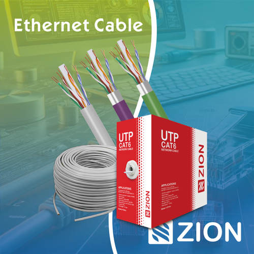 Ethernet Cable
 Coaxial Cable
 Fire & Security Cable
 Voice, Audio & Video
 Power & Control Cable