
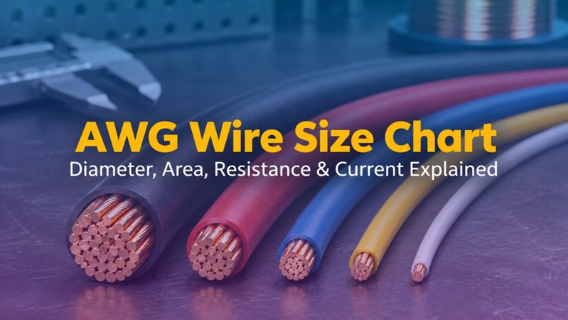
What is the diameter of 24 AWG wire?
A solid 24 AWG conductor has a nominal bare diameter of about 0.511 mm and a cross-sectional area of about 0.205 mm². Insulation increases the finished conductor diameter.
Author: Site Editor Publish Time: 16-11-2026 Origin: Site
Use this reference to convert American Wire Gauge to millimeters and square millimeters, compare copper resistance, and avoid the most common mistake in wire selection: treating one ampacity chart as universal.
AWG stands for American Wire Gauge, a dimensional system for round electrical conductors. It is a reverse scale: 12 AWG is larger than 18 AWG, and 24 AWG is larger than 28 AWG.
The system is based on a geometric progression. NIST describes 4/0 AWG as 0.4600 inch in diameter and 36 AWG as 0.0050 inch, with 39 equal ratio steps between them. This produces a diameter ratio of approximately 1.12293 between adjacent sizes.
AWG describes the bare metallic conductor. It does not include insulation, shielding or the outer cable jacket. Solid and stranded conductors with the same nominal AWG also differ in construction and finished diameter.
The table below converts AWG to nominal bare diameter and cross-sectional area. Copper resistance is calculated for a solid annealed-copper conductor at 20°C using a resistivity of 0.017241 Ω·mm²/m. Actual cable values vary with material, stranding, manufacturing tolerance and temperature.
| AWG | Diameter (mm) | Area (mm²) | Approx. copper resistance at 20°C (Ω/km) |
|---|---|---|---|
| 4/0 | 11.684 | 107.219 | 0.161 |
| 3/0 | 10.405 | 85.029 | 0.203 |
| 2/0 | 9.266 | 67.431 | 0.256 |
| 1/0 | 8.251 | 53.475 | 0.322 |
| 1 | 7.348 | 42.408 | 0.407 |
| 2 | 6.544 | 33.631 | 0.513 |
| 3 | 5.827 | 26.670 | 0.646 |
| 4 | 5.189 | 21.151 | 0.815 |
| 5 | 4.621 | 16.773 | 1.028 |
| 6 | 4.115 | 13.302 | 1.296 |
| 7 | 3.665 | 10.549 | 1.634 |
| 8 | 3.264 | 8.366 | 2.061 |
| 9 | 2.906 | 6.634 | 2.599 |
| 10 | 2.588 | 5.261 | 3.277 |
| 11 | 2.305 | 4.172 | 4.132 |
| 12 | 2.053 | 3.309 | 5.211 |
| 13 | 1.828 | 2.624 | 6.571 |
| 14 | 1.628 | 2.081 | 8.285 |
| 15 | 1.450 | 1.650 | 10.448 |
| 16 | 1.291 | 1.309 | 13.174 |
| 17 | 1.150 | 1.038 | 16.612 |
| 18 | 1.024 | 0.823 | 20.948 |
| 19 | 0.912 | 0.653 | 26.415 |
| 20 | 0.812 | 0.518 | 33.308 |
| 21 | 0.723 | 0.410 | 42.001 |
| 22 | 0.644 | 0.326 | 52.962 |
| 23 | 0.573 | 0.258 | 66.784 |
| 24 | 0.511 | 0.205 | 84.213 |
| 25 | 0.455 | 0.162 | 106.191 |
| 26 | 0.405 | 0.129 | 133.904 |
| 27 | 0.361 | 0.102 | 168.850 |
| 28 | 0.321 | 0.081 | 212.916 |
| 29 | 0.286 | 0.064 | 268.482 |
| 30 | 0.255 | 0.051 | 338.550 |
| 31 | 0.227 | 0.040 | 426.904 |
| 32 | 0.202 | 0.032 | 538.315 |
| 33 | 0.180 | 0.025 | 678.803 |
| 34 | 0.160 | 0.020 | 855.955 |
| 35 | 0.143 | 0.016 | 1079.339 |
| 36 | 0.127 | 0.013 | 1361.022 |
| 37 | 0.113 | 0.010 | 1716.217 |
| 38 | 0.101 | 0.008 | 2164.110 |
| 39 | 0.090 | 0.006 | 2728.892 |
| 40 | 0.080 | 0.005 | 3441.069 |
Reference values are rounded. For purchasing, compliance or acceptance testing, use the applicable product specification and standard rather than calculated nominal values alone.
First calculate the bare conductor diameter, then use the circular-area formula:
For example, 24 AWG has a nominal diameter of 0.511 mm:
Do not round an AWG size to the nearest metric cable size and assume the products are interchangeable. Standards, strand construction, insulation system, temperature rating and allowable resistance can differ even when the nominal areas look similar.
AWG determines conductor geometry, but ampacity is a thermal and installation limit. The same gauge may have different allowable current depending on how effectively heat can leave the conductor.
NFPA's NEC ampacity workflow uses conductor ampacity tables together with ambient-temperature correction and adjustment factors. That is why a bare “AWG-to-amps” column is not enough for safe power-circuit design.
Ethernet cable selection is not the same as selecting a single power conductor. Balanced twisted-pair cable carries signals over controlled pairs, and PoE sends power through two or four pairs under IEEE 802.3 rules. IEEE 802.3bt extends standardized PoE delivery by using all four pairs.
For PoE, conductor size matters because smaller conductors generally have higher DC resistance. Higher resistance increases voltage drop and heat, especially in large cable bundles. TIA's TSB-184 guidance therefore considers current per pair, bundle conditions, pathways and temperature rise—not AWG alone.
| Typical gauge | Nominal diameter | Practical cabling implication |
|---|---|---|
| 22 AWG | 0.644 mm | Lower conductor resistance, but a larger and less flexible cable construction. |
| 23 AWG | 0.573 mm | Common in higher-performance horizontal cables where resistance and thermal margin matter. |
| 24 AWG | 0.511 mm | Widely used for Category 5e horizontal cable; confirm the complete cable's standards and PoE rating. |
| 26 AWG | 0.405 mm | More flexible, with higher resistance; often used in cords or compact constructions subject to length limits. |
| 28 AWG | 0.321 mm | High-density patching benefit, but power delivery and channel-length rules require specific verification. |
AWG alone does not identify conductor material. A 24 AWG copper conductor and a nominally 24 AWG copper-clad aluminum (CCA) conductor may share a similar diameter, but they are not electrically equivalent.
Material affects DC resistance, voltage drop, heat generation, mechanical behavior, termination compatibility and compliance. UL guidance requires aluminum and copper-clad aluminum wiring products to carry material identification where applicable. For communications projects, specify both the gauge and conductor material, then verify the finished cable against the required category and safety certification.
A solid 24 AWG conductor has a nominal bare diameter of about 0.511 mm and a cross-sectional area of about 0.205 mm². Insulation increases the finished conductor diameter.
No. AWG is a reverse scale: a higher gauge number means a smaller conductor diameter and cross-sectional area.
There is no universal amp rating for an AWG size. Allowable current depends on conductor material, insulation temperature rating, ambient temperature, bundling, installation method, circuit rules and applicable electrical code.
24 AWG bare-copper conductors are widely used in Category 5e horizontal cable. PoE suitability must still be confirmed against the cable category, DC resistance, resistance unbalance, temperature rating, bundle size and the applicable IEEE and cabling installation guidance.
No. Two conductors can share the same nominal diameter while having different conductivity, resistance, voltage drop, heating behavior and compliance status. Material must be specified separately from AWG.
Certification and compliance references for project review, qualification and purchasing documentation.

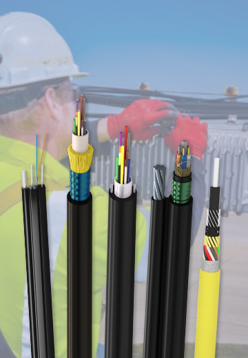 Fiber Optic CableAccess and backbone
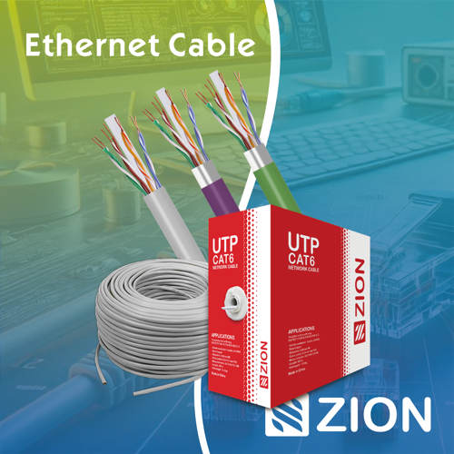 Ethernet CableCat5e to Cat8
 Coaxial CableRF and video signal
 Fire, Security & AlarmSafety systems
 Voice, Audio & VideoSignal cabling
 Power & Control CableEnergy and control
Outdoor, indoor, FTTH and distribution cable lines for access networks, backbone routes and campus deployments.
 Telecom & ISP NetworksFTTH, PON, ODN
 Data Center InfrastructureServer room cabling
 Building Low-Voltage SystemsBMS, AV, weak current
 Security & Fire ProtectionAlarm, CCTV, access
 Industrial Automation CablePLC, RS485, fieldbus
 Energy & Power InfrastructureSolar, battery, power
For FTTH / PON access, outdoor fiber deployment, aerial routes, duct routes, direct burial routes, rural broadband and ODN planning.
Use calculators and planning tools for conduit capacity, PoE voltage drop and fiber optic link loss budget work.



 Fiber Optic Tools
