

This guide covers passive fiber distribution using optical distribution frames (ODFs) and rack-mounted fiber patch panels. Product terminology varies by supplier: a patch panel may form part of an ODF system, while other installations use panels directly in equipment racks. The required functions and physical arrangement matter more than the product label.
Start with the network and optical interfaces
Map the links that will use structured fiber cabling. A centralized ODF is not necessary for every cluster connection; choose distribution points according to the topology, permitted channel length, loss budget, and maintenance requirements.
Record the following for each link group:
- Source, destination, and network role.
- Switch and transceiver part numbers, operating mode, and supported breakout configuration.
- Fiber type, connector format, polish, and active fiber positions.
- Trunks, patch cords, cassettes, and connections along the complete route.
- Routed length, application loss limit, and initial and future link counts.
The data rate alone does not identify the cabling. For example, Cisco specifies duplex LC for its QDD-400G-FR4-S module and MPO-12 APC for its QDD-400G-DR4-S module. Both are 400G products, but they require different physical connectivity.
At 800G, connector arrangements also vary. Cisco lists dual MPO-12 APC and single MPO-16 APC implementations for different OSFP-800G-DR8 models. Select against the exact part number and platform requirements.
Define what panel density means
A specification such as “96 ports” is incomplete without a counting convention. Distinguish adapter positions, terminated fibers, and usable links for the selected application.
As a counting example, 48 fully populated duplex LC adapter positions accommodate 96 fiber terminations and up to 48 two-fiber duplex links at that panel. This is not a claim about any particular panel's rack height or tested capacity. Usable end-to-end capacity also depends on the trunks and equipment at the other end.
MPO position count is different from active fiber count. NVIDIA's MMA4Z00-NS-T twin-port module has two MPO-12/APC interfaces; each uses eight fibers for its 400G optical connection. Twelve positions therefore do not mean twelve active fibers in that application.
Compare proposals on a common basis:
| Procurement item | What to establish |
|---|---|
| Panel termination capacity | Connector format, populated positions, and fiber count per U |
| Application capacity | Usable links and active fibers per link |
| Complete rack arrangement | Panel space plus horizontal management and vertical routing space |
| Maintenance access | Reach, visibility, and tool clearance at full population |
| Expansion capacity | Remaining modules, pathways, manager capacity, and optical margin |
Ask for a drawing or demonstration of the proposed configuration fully patched with representative cable diameters, boots, and routing accessories.
Check maintenance access and closed-door clearance separately
Evaluate normal maintenance with the access doors open and any trays in their intended service positions. A technician should be able to identify and release a connection in the middle of a populated panel without pulling on neighboring cords. Check clearance for inspection probes, cleaning tools, connector boots, and release tabs.
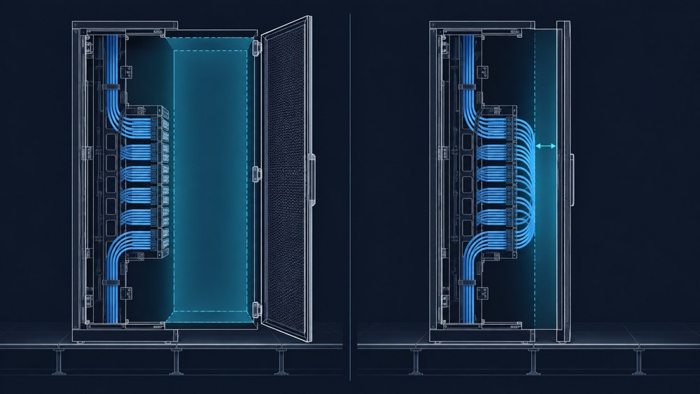
Then return the assembly to its operating position and close the doors. Verify that cords are not compressed, bend limits are maintained, and the door does not contact connectors or strain-relief boots.
Sliding and pivoting mechanisms require controlled cable movement throughout their travel. Verify both front patch cords and rear trunks when the panel opens, moves, and closes. A mechanism that works with an empty enclosure may become difficult to operate after patching.
Use an uncommissioned sample or an approved maintenance window for demonstrations that involve disconnecting fibers.
Plan cable entry, rear access, and slack together
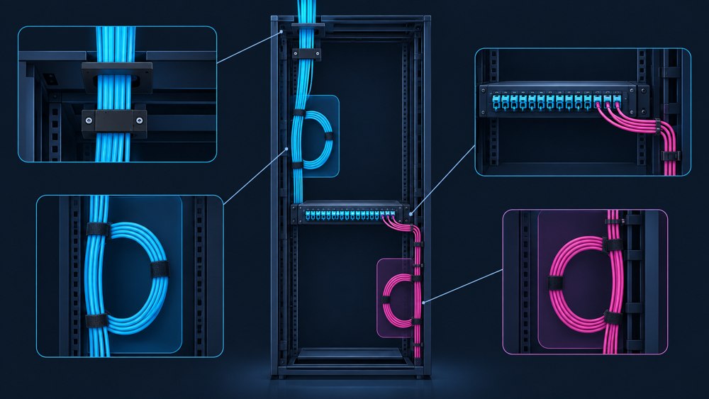
A front-serviceable product still needs an installation method for incoming trunks and future additions. Establish how technicians will secure cables, reach rear interfaces or splice trays, and replace a damaged module.
Coordinate these activities with adjacent equipment, power distribution, containment, and cooling service areas. Where liquid cooling is present, preserve the required access to hoses and manifolds.
Route cables through designated guides and strain relief so connector interfaces do not carry the cable load. Follow the specified bend radius and tensile limits for each cable assembly. Installation under tension and the final unloaded condition may have different bend limits.
Allocate separate storage for trunk service loops, splice-tray fibers, and patch-cord slack. Choose patch-cord lengths from the actual managed route, including the allowance needed for servicing movable components. Repeated excess loops can consume the space reserved for expansion.
Where physical route diversity is required, check separation through the distribution area as well as along the main pathways.
Specify the complete MPO or LC connection scheme
LC patching and MPO connectivity can coexist within one installation. Select them around the optical interfaces and the intended patching architecture. For component options, review HelloSignal’s MPO/MTP cable assemblies and patch panels.
For LC connections, specify fiber type, polish, duplex arrangement where applicable, polarity, and access requirements. For MPO connections, also document the connector format, populated and active positions, pinned or unpinned interfaces, adapter key orientation, and end-to-end fiber mapping.
Treat polarity as an end-to-end design property. A trunk's Type A, B, or C designation alone does not describe a channel containing patch cords, adapters, and cassettes. Verify the complete assembly and its mating interfaces.
An ordinary passive MPO-to-LC cassette redistributes fibers between connector formats. It does not convert optical signaling, wavelengths, or data rates. A breakout arrangement requires compatible optics, lane mapping, and host-port configuration. Compare enclosure and module options in ZION’s MPO patch panel and cassette range.
Neither an LC nor an MPO connector, by itself, establishes compatibility with 400G, 800G, or a future application.
Calculate loss for each optical path
Prepare the loss calculation from the actual components on each path: fiber attenuation at the relevant wavelength, mated connector pairs, splices, and any other passive elements. Use specified maximum losses rather than relying only on typical values, and retain a project-defined engineering margin.
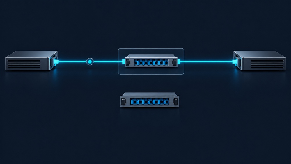
Document what each component specification includes. If a cassette's end-to-end loss already covers its interfaces, counting those interfaces again would overstate the total.
Adding a cassette in an unused panel position does not, by itself, increase the loss of existing channels. Recalculate when a new or rerouted channel passes through additional connections or components.
Compare the result with the selected application's insertion-loss limit and length limit. Passing a loss calculation alone does not establish full application compatibility. Use the ZION MPO/MTP Link Planner to organize an initial configuration and loss estimate, then confirm the result against the module datasheet, project requirements, and actual test reports.
For parallel optics, verify each active fiber path rather than treating an average loss across an MPO assembly as sufficient. Include reflectance or return-loss requirements where specified by the application or project.
Reserve a complete expansion route
An empty module slot is only one part of expansion capacity. Review future trunk entry, pathway space, cable-manager loading, slack storage, maintenance clearance, and optical requirements together.
Set reserve capacity from the deployment plan. A single spare-capacity percentage will not describe every site's needs.
For a future optics change, recheck fiber type, connector format, active fiber count, polarity, reach, and loss limits. A modular enclosure can make changes easier, but does not guarantee that the existing cabling will support a new interface.
Define acceptance and records before installation
Use a representative populated assembly to verify circuit identification, connector release, tool access, patch-cord replacement, and tray movement. Record whether these tasks can be completed without disconnecting unrelated links.
Before mating connectors, inspect the end faces, clean when needed, and reinspect after cleaning using suitable tools and the project's acceptance criteria. IEC 61300-3-35:2022 addresses visual inspection; it explicitly states that this does not replace optical performance measurements. IEC 61300-3-35:2022
Define the field-test boundary and method in advance. Record whether results cover a permanent link or the complete channel, along with the reference method, test wavelengths, applicable limits, and fiber or circuit identifiers. Verify continuity, polarity, length, and insertion loss as required by the project, with additional measurements where specified.
Factory records support component checks. They do not certify the completed installation.
Keep identifiers visible after patching. A local format such as DC1-R03-PP02-P024 can identify a panel position; for MPO assemblies, add fiber-position and breakout mapping records. Update these records whenever connections change.
Specify Your ZION Fiber Distribution Package
When evaluating ZION ODFs, fiber patch panels, and patch cords, start with the rack layout, connection schedule, transceiver part numbers, and expansion plan.
Use these inputs to request a coordinated bill of materials covering the enclosure, modules, adapters, cable assemblies, managers, and labeling. The ZION data center passive cabling guide provides a starting point for organizing that package. For each proposed configuration, request the populated layout, mechanical dimensions, connection map, specified optical performance, and applicable test documentation.
The final selection should make clear what technicians can install, reach, replace, and expand at the planned density. This gives procurement, design, and operations teams a shared basis for reviewing the passive fiber infrastructure.
Prepare Your Project Request
Share your rack layout, connection schedule, transceiver part numbers, quantities, expansion stages, and test requirements for a configuration and bill-of-materials discussion.
Request Project Support


