
1. The terminal converts service data into an optical signal
Control commands, video, telemetry or sensor data enter an optical terminal before being modulated onto an optical carrier. The service side may use Ethernet or a serial interface; the fiber side must match the optical module, fiber type and connector system.
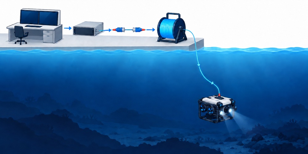
The published ZION underwater fiber-optic spool specifications identify FC/UPC or LC/UPC on the optical side. Here, FC is a connector type—not evidence of Fibre Channel protocol support. The listed 1310 nm and 1550 nm wavelength choices also do not, by themselves, define a simplex, dual-fiber duplex, single-fiber bidirectional or WDM/BiDi architecture.
Specify Ethernet or serial standard, data rate, protocol, upstream/downstream bandwidth, latency and target BER.
Specify fiber count, duplex method, wavelength pair, launch power, receiver sensitivity, overload level and allowed channel loss.
Confirm input voltage, power consumption, grounding, start-up behavior and operation after link loss.
Confirm terminal enclosure, connector location, cable exit, strain relief and installation envelope.
2. The spool pays out micro-cable according to the mission design
The spool stores and releases micro-cable to create a continuous guided optical path between two endpoints. Whether it travels with the underwater vehicle, remains at the surface or operates as part of a paired payout arrangement depends on the mission architecture.
ZION lists G.657.A2 bend-insensitive single-mode fiber with aramid reinforcement and a PVC jacket, cable diameters of 0.5 mm and 0.65 mm, and tensile figures above 150 N and 200 N. These values describe important components, but they do not replace finished-cable and deployment data.
- The 7.5 mm value associated with ITU-T G.657.A2 is a standard reference condition for fiber macrobending performance, not a universal dynamic bend radius for the finished cable.
- A tensile figure does not qualify micro-cable to tow, recover or restrain a vehicle. Load-bearing service requires a defined working load, safety factor and cycle-test evidence.
- The listed 1–30 km range is cable loaded on the spool. Routing, slack, reserve length and mission geometry reduce practical reach.
“High-speed optical fiber release device” should be read as a product description unless a payout speed and its test conditions are stated. It is not a data-rate specification.
3. The connection and sealing structure bridge wet and dry zones
Connectors, penetrators, pigtails or potted transitions bring the fiber into an enclosure. A project must distinguish a sealed dry-mate connection from a pressure-rated wet-mate connector because they have different installation and maintenance requirements.
A PVC jacket, sealed connector or waterproof housing does not individually establish the pressure rating of the complete system. IEC 60794-1-210:2026 defines hydrostatic-pressure test methods for optical cables; a project test report should identify the sample, applied pressure, duration and acceptance criteria. The connector, terminal enclosure and complete spool assembly require their own applicable verification.
4. The receiving terminal restores the service data
At the other endpoint, the receiving terminal converts the optical signal back into Ethernet, serial data or another service format. Light guided in glass fiber does not couple to external electromagnetic fields in the same way as a copper conductor, which makes fiber useful in high-EMI environments. Power inputs, terminals, copper-side interfaces, bonding and metallic housings still require EMC engineering.
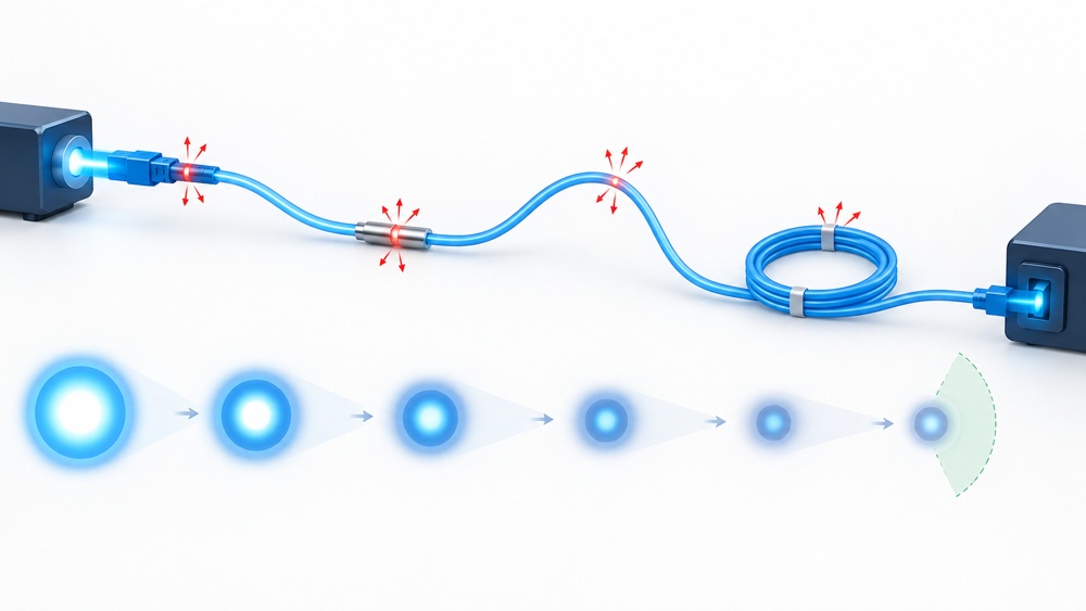
End-to-end reliability also depends on clean connector end faces, connection reflectance, microbending and macrobending, payout tension, optical-module temperature drift, power quality, protocol configuration and software behavior.
5. How to interpret the published figures
Manufacturer-listed values are useful inputs to a design review. Each value should be connected to a defined system requirement and an acceptance method.
| Published value | Sound interpretation | Additional verification |
|---|---|---|
| 1–30 km length | Available cable length on the spool | Route reserve, mission geometry and complete optical budget |
| G.657.A2 | Bend-insensitive single-mode fiber category compatible with G.652.D | Finished-cable static and dynamic bend limits under tension |
| ≤0.35 dB/km at 1310 nm | Up to about 10.5 dB nominal fiber attenuation over 30 km | Connections, bends, deployment penalties and engineering margin |
| ≤0.25 dB/km at 1550 nm | Up to about 7.5 dB nominal fiber attenuation over 30 km | Launch power, receiver sensitivity and overload limits |
| >150 N / >200 N | Listed tensile figures for the two cable sizes | Working load, safety factor, termination strength and cycle testing |
| −40°C to +60°C | A listed temperature range | Applicable component, operating/storage state and combined pressure conditions |
A channel-loss budget should include fiber attenuation, every mated connection or splice, bending and deployment penalties, plus engineering margin. The result must remain within worst-case launch power and receiver sensitivity while respecting receiver-overload limits.
6. A reliable procurement and verification sequence
Use the following order to turn a spool specification into a complete link requirement:
- Define the mission architecture: platform type, endpoint locations, expendable or recoverable deployment, maximum speed, turning path and mission duration.
- Define the service: interfaces, protocols, upstream/downstream bandwidth, duplex method, latency, BER and safe behavior after link loss.
- Build the optical budget: use worst-case fiber, connection, bend, temperature and ageing losses with engineering margin.
- Check payout mechanics: payout direction, dynamic bend radius, working and peak tension, abrasion, twist, buoyancy or sinking behavior and installation envelope.
- Specify the environment: working depth, hydrostatic pressure, hold time, seawater compatibility, temperature, shock, vibration and connector mating method.
- Agree on acceptance evidence: end-to-end insertion loss, OTDR traces, pressure and payout tests, interface integration, BER or throughput testing and serial-number-traceable reports.
7. Frequently asked questions
Is a deployable underwater fiber link the same as underwater wireless optical communication?
No. A deployable fiber link guides light inside a physical fiber. Underwater wireless optical communication sends an unguided optical beam through water.
Does a 30 km spool guarantee a 30 km working link?
No. The spool length must be reduced by routing, slack and reserve requirements, and the complete channel must remain within the transceiver optical budget.
Can G.657.A2 micro-cable be used as a load-bearing ROV umbilical?
Not on the fiber category alone. Load-bearing service requires a defined working load, safety factor, dynamic bend radius and cycle-test evidence for the finished cable assembly.
Which information is needed before requesting a quotation?
Provide the platform and deployment method, required cable length, interfaces and data rate, duplex topology, working depth and pressure conditions, payout speed and tension, connector type, test requirements and quantity.
Technical references
- ITU-T G.657 (08/2024): Bend-insensitive single-mode optical fiber and cable
- IEC 60794-1-210:2026: Underwater cable resistance to hydrostatic pressure
- The Fiber Optic Association: Power budgets and loss budgets
- Underwater optical wireless communications, networking, and localization: A survey
Prepare the link requirements before quotation
Send the platform type, deployment method, fiber length, interface and data-rate requirements, working depth, payout conditions, connector preference, quantity and required acceptance tests.
Request Project Support


