How to Compare Radiating Cable Coupling Loss Data | ZION
Author: Site Editor Publish Time: 11-11-2026 Origin: Site
How to Compare Radiating Cable Coupling Loss Data
Align measurement conditions before judging whether loss figures are suitable for procurement and system design.
■ Separate coupling loss from longitudinal attenuation
Radiating cable coupling loss describes transfer between the cable and a receiving antenna under a defined measurement arrangement. Longitudinal attenuation describes signal reduction along the cable. They answer different questions: how much signal reaches a location along the route, and how effectively that location couples to an antenna.
A lower coupling-loss figure alone does not establish the best cable for the complete route. The system designer must consider both losses at the operating frequency, together with the feed arrangement and other components. ZION’s radiating leaky coaxial cable range is a starting point for identifying candidate models; request the model-specific electrical data before comparing them.
■ Align frequency and units first
Compare values at the same frequency, not simply within the same advertised frequency band. Record whether each value is typical, a limit or a measured result. Missing test points should be requested rather than silently interpolated.
Coupling loss is normally expressed in dB, while longitudinal attenuation may be expressed in dB/100 m or another length basis. Normalize attenuation units before using the route length. Do not multiply a coupling-loss value by cable length as though it were attenuation per metre.
■ Identify the measurement arrangement
Ground-level and free-space measurements are different arrangements. Record the method, surrounding surfaces, cable position, receiving-antenna separation and scan path. A shared standard number without these details is not sufficient evidence of identical conditions.
Do not apply a universal correction between methods or assume that one method always gives the lower loss. When conditions differ, mark the comparison as conditional and request matched data. IEC 61196-1-124:2022 specifically addresses coupling-loss testing; record the exact standard and edition cited in each report and check the project’s applicable requirements.
■ Keep antenna orientation and statistics separate
Confirm whether the result is for a radial, parallel or orthogonal antenna orientation, or an average obtained using a stated calculation. An orientation average is not automatically an arithmetic average of the listed dB values. Ask for the calculation basis when it is absent.
Also record the statistical designation, such as C50 or C95, and its definition in the report. Compare like with like. A result labelled C50 should not be ranked directly against C95. These measurement statistics do not by themselves promise a corresponding percentage of coverage throughout the finished tunnel.
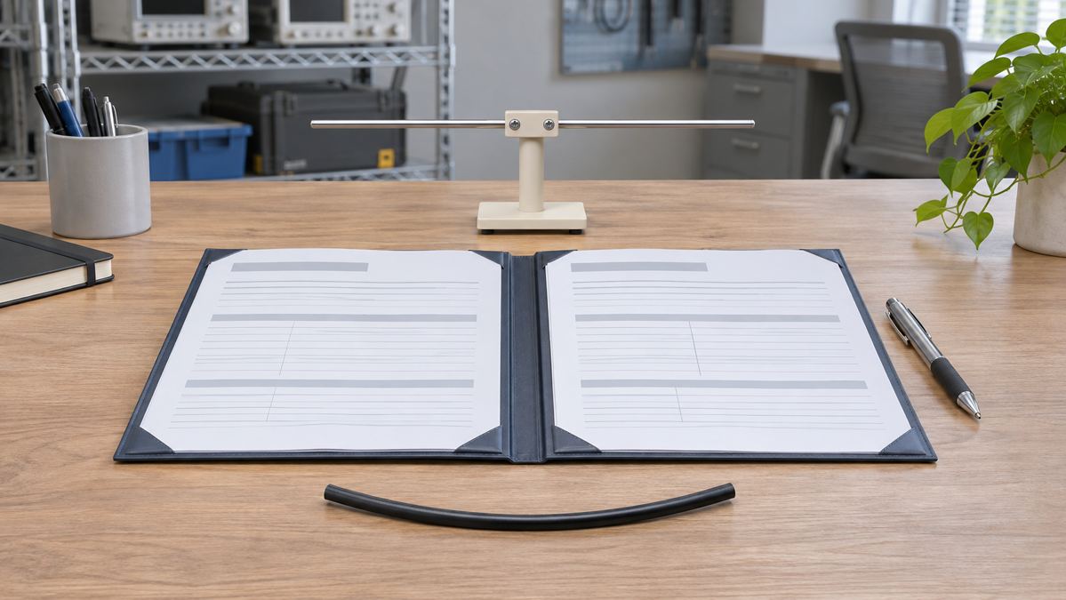
AI-generated datasheet review illustration; not a standardized test arrangement or an actual ZION product photograph.
■ Build a supplier comparison record
Create one record for each candidate and each required frequency. Use the same field names for both suppliers, attach the source documents, and leave unknown fields explicitly marked “pending confirmation.”
Model and document
Exact model, datasheet revision, report reference and issuing organization.
Supplier A: ________ Supplier B: ________
Frequency and values
Test frequency, coupling loss in dB, attenuation unit, and typical or limit status.
Supplier A: ________ Supplier B: ________
Method and geometry
Standard edition, ground-level or free-space method, separation, mounting and surroundings.
Supplier A: ________ Supplier B: ________
Antenna and evaluation
Antenna type, orientation or averaging method, C50/C95 definition and scan basis.
Supplier A: ________ Supplier B: ________
Decision and owner
Comparable, conditional or pending; missing evidence, responsible reviewer and review date.
Supplier A: ________ Supplier B: ________
■ Use comparable data for design, then verify the installed system
A datasheet comparison supports material selection; it is not a site acceptance test. Give the system integrator the route length, geometry, installation environment, feed locations and required services so that the appropriate link budget and verification plan can be established.
For a simple one-end-fed section, longitudinal loss to the location and the selected coupling-loss figure are inputs to the calculation. Connector, feeder and splitter losses, equipment levels, antenna assumptions and project margins must also be addressed. More complex feed arrangements require their own design model. Agree the coverage locations, test equipment, operating conditions and acceptance criteria before installation.
For a datasheet review, send ZION the working frequency bands, route length, installation environment, coverage targets and the candidate datasheets. Identify missing measurement conditions before approving a procurement comparison.



 Fiber Optic Tools
Products 6 families
Solutions 6 markets
Resources Tools & docs
Certificate
Certification and compliance references for project review, qualification and purchasing documentation.

 Fiber Optic CableAccess and backbone
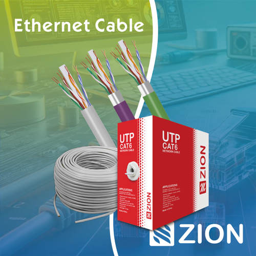 Ethernet CableCat5e to Cat8
 Coaxial CableRF and video signal
 Fire, Security & AlarmSafety systems
 Voice, Audio & VideoSignal cabling
 Power & Control CableEnergy and control
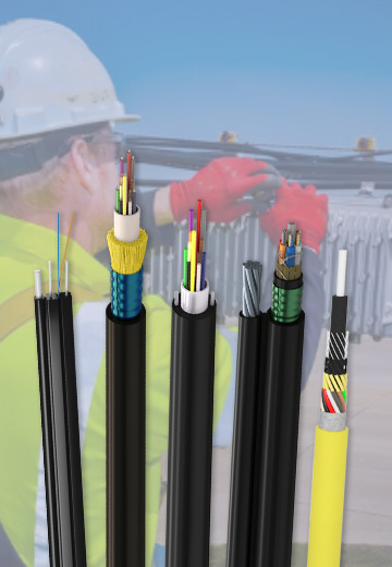
Fiber optic cable systems
Outdoor, indoor, FTTH and distribution cable lines for access networks, backbone routes and campus deployments.
 Telecom & ISP NetworksFTTH, PON, ODN
 Data Center InfrastructureServer room cabling
 Building Low-Voltage SystemsBMS, AV, weak current
 Security & Fire ProtectionAlarm, CCTV, access
 Industrial Automation CablePLC, RS485, fieldbus
 Energy & Power InfrastructureSolar, battery, power
Telecom & ISP Networks
For FTTH / PON access, outdoor fiber deployment, aerial routes, duct routes, direct burial routes, rural broadband and ODN planning.
Tools
Use calculators and planning tools for conduit capacity, PoE voltage drop and fiber optic link loss budget work.