RS485 Cable Selection Guide: Impedance and Installation | ZION
Author: Michael Publish Time: 28-07-2025 Origin: Site
RS485 Cable Selection Guide
Select RS485 cable by checking impedance, conductor resistance, baud rate, topology and installation conditions against equipment requirements before ordering.
■Choose cable against the equipment requirements
RS-485 defines electrical signaling, not a complete application protocol or a universal cable-distance guarantee. Identify the actual protocol and interface: for example, Modbus RTU or BACnet MS/TP where the equipment specifies RS-485. Use the device wiring instructions to establish pair count, reference connections and approved cable requirements.

■Separate impedance, conductor resistance and termination resistance
Characteristic impedance describes transmission-line behavior and is specified with relevant frequency and tolerance conditions. Conductor DC resistance describes resistance along a stated conductor length at a stated temperature. A termination resistor is a circuit component selected for the line design. All use ohms, but they are not interchangeable. A DC resistance measurement does not directly establish cable characteristic impedance.
■Use 120 Ω as a common design reference, not a universal approval
A nominal 120 Ω differential pair is common in RS-485 designs. Confirm the actual cable specification and termination arrangement against the equipment manual. Do not impose 120 Ω ±10% as a universal requirement unless the project or product specification calls for it. Record both the tolerance and measurement conditions. For a conventional two-wire bus using parallel termination, the usual locations are the two physical ends of the main bus, not every device. Check built-in termination before adding external resistors. Some engineered short or slow links may omit termination; this needs design validation, not a blanket distance rule.
■Check conductor material and measured electrical data
Specify conductor material, nominal cross-section and maximum DC resistance with units and reference temperature. CCA must not be described as causing signal loss because of very low resistance. At comparable geometry, its aluminum-containing construction generally has higher resistance than an all-copper conductor; evaluate the actual construction and documented data rather than a marketing label. Do not assume solid conductors always provide better long-distance performance than stranded conductors. Termination compatibility, resistance and the complete transmission specification matter.
■Evaluate distance together with baud rate and topology
There is no single distance table that guarantees every RS-485 installation. Increasing baud rate is not a method for extending cable reach. Evaluate cable attenuation and capacitance, propagation delay, driver edge rate, receiver capability, loading, topology and interference. Lowering baud rate may help some designs but does not correct every wiring or grounding problem. A repeater creates an additional segment whose limits and timing must be checked; it is not an unlimited-range guarantee.
■Coordinate shielding, reference connections and installation
Route each differential signal on a twisted pair and keep branches consistent with the equipment design. A two-wire data pair does not mean that signal-reference, protective bonding or other specified connections can be omitted. Keep signal reference, protective earth and cable shield functions distinct. Select shielding and its termination according to the equipment EMC instructions and site bonding design; do not universally prescribe one-end, both-end or non-master-end grounding. Assess ground-potential differences and any required isolation or surge protection. Shielding does not make an indoor jacket suitable for outdoor exposure.

■Procurement parameter checklist
Protocol and equipment
Protocol/version, exact device models and wiring manuals
Rate and route
Baud rate, total segment length, individual branches and node locations
Topology and loading
Two/four-wire arrangement, node loading, repeaters and termination/biasing plan
Cable transmission data
Characteristic impedance and tolerance, test frequency, capacitance and relevant attenuation data
Conductor and terminals
Material, nominal area, DC resistance and temperature, terminal preparation requirements
Environment
Temperature, moisture/UV, chemicals, routing, bend and movement requirements
Evidence and release
Datasheet revision, agreed test plan, acceptance criteria and unresolved items
Send the equipment requirements, route drawing, baud rate, quantities and required cable documentation to ZION for review. Confirm the complete cable specification before approving substitutions.



 Fiber Optic Tools
Products 6 families
Solutions 6 markets
Resources Tools & docs
Certificate
Certification and compliance references for project review, qualification and purchasing documentation.
 Fiber Optic CableAccess and backbone
 Ethernet CableCat5e to Cat8
 Coaxial CableRF and video signal
 Fire, Security & AlarmSafety systems
 Voice, Audio & VideoSignal cabling
 Power & Control CableEnergy and control
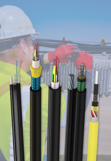
Fiber optic cable systems
Outdoor, indoor, FTTH and distribution cable lines for access networks, backbone routes and campus deployments.
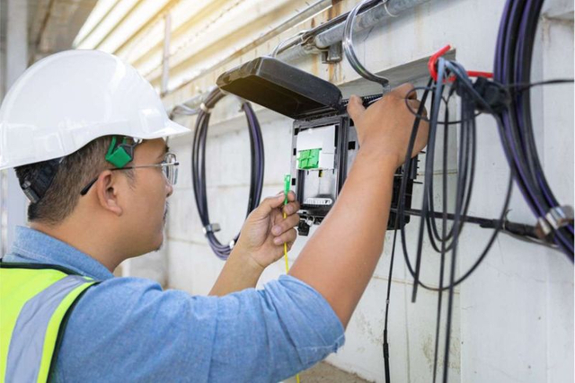 Telecom & ISP NetworksFTTH, PON, ODN
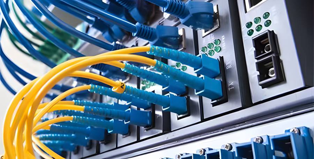 Data Center InfrastructureServer room cabling
 Building Low-Voltage SystemsBMS, AV, weak current
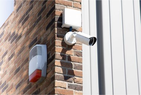 Security & Fire ProtectionAlarm, CCTV, access
 Industrial Automation CablePLC, RS485, fieldbus
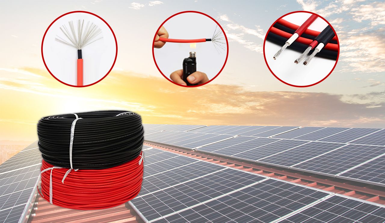 Energy & Power InfrastructureSolar, battery, power
Telecom & ISP Networks
For FTTH / PON access, outdoor fiber deployment, aerial routes, duct routes, direct burial routes, rural broadband and ODN planning.
Tools
Use calculators and planning tools for conduit capacity, PoE voltage drop and fiber optic link loss budget work.