
1. Confirm that the link architecture fits the mission
Define the platform, control concept, mission duration, data type, loss-of-link behavior, and recovery plan before requesting a quotation. The key engineering boundary differs by platform.
A 0.5 mm or 0.65 mm micro-cable should not be treated as a load-bearing powered umbilical. The vehicle needs a separate power source, with mechanical load and link-loss risks assessed.
Evaluate the spool for mission-specific communication, test, or intervention architectures. The term AUV does not itself imply continuous real-time control.
Distinguish single-use payout, recoverable temporary links, and permanent subsea installation before selecting a spool for long-duration service.
Also specify whether payout occurs from the vehicle, the receiving station, or both ends, and which end carries hydrodynamic drag during deployment. This choice affects installation, reserve length, and risk.
2. Size deployed length from the route, not straight-line radius
The ZION underwater fiber optic spool page currently lists 1–30 km length options. Required length should cover the planned track, deployment route, added path caused by depth and terrain, termination and test leads, plus an engineering reserve for navigation error and obstacle avoidance.
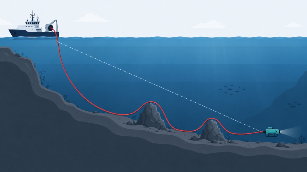
A 20 km spool therefore does not provide a guaranteed 20 km straight-line operating radius. Reserve should be derived from mission uncertainty, sea conditions, and payout method rather than a universal percentage.
3. Interpret the 0.5 mm and 0.65 mm constructions correctly
The product page presents two nominal parameter sets in the same order. The supplier should map each value to a specific configuration, test method, and acceptance condition in the purchase documents.
| Nominal diameter | Nominal mass | Published tensile value | Nominal density |
|---|---|---|---|
| 0.5 mm | 248 g/km | >150 N | 1.25 g/cm³ |
| 0.65 mm | 430 g/km | >200 N | 1.3 g/cm³ |
Mechanical selection also needs short-term maximum load versus allowable continuous working tension, gauge length, loading rate, added attenuation or residual strain after tensile loading, minimum static and dynamic bend radii, allowable payout speed, minimum tension, and jam load.
4. Check length and wavelength with an optical loss budget
The published maximum micro-cable attenuation is ≤0.35 dB/km at 1310 nm and ≤0.25 dB/km at 1550 nm. Cable attenuation alone gives a maximum theoretical one-way loss of 10.5 dB at 1310 nm or 7.5 dB at 1550 nm over 30 km.
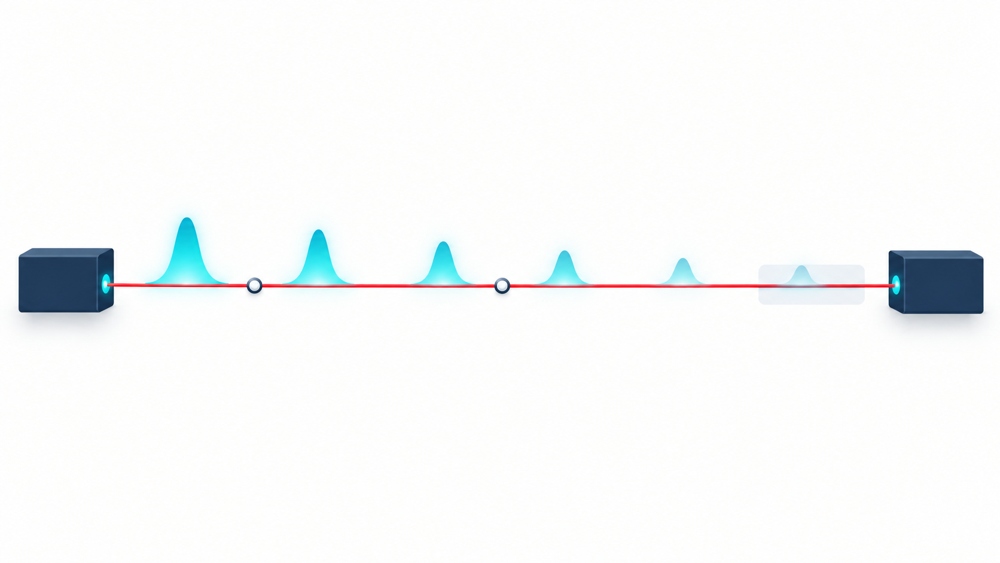
Available budget depends on transmitter launch power and receiver sensitivity. Connectors, splices, bending, payout, temperature, and pressure can add loss, so wavelength and spool length alone cannot establish whether a 30 km link will operate.
ITU-T G.657.A2 identifies a bend-loss-insensitive single-mode fiber category. It defines fiber bending-performance boundaries; it is not an underwater pressure, abrasion, or dynamic-payout qualification.
5. Separate optical, service, and subsea interfaces
The page lists FC/UPC or LC/UPC for the spool optical interface. Its terminal table lists an FC optical port, network port, and serial port, with 1310 nm or 1550 nm options. Project documents should also define:
- single-fiber bidirectional or dual-fiber operation and fiber count;
- Ethernet data rate, serial electrical standard, and supported protocols;
- launch power, receiver sensitivity, and allowable error rate;
- FC/LC connection locations, plug/adapter arrangement, and UPC polish;
- subsea connector model, contact count, pressure rating, mating life, and wet-mate capability; and
- vehicle- and surface-side supply voltage, power, inrush current, and grounding.
6. Verify mechanical integration without extrapolating dimensions
The current page gives reference envelopes for 10 km and 20 km configurations. It describes the can material as “resin & metallic aluminum”; the project documents should clarify whether these materials are combined or optional.
| Nominal spool length | Reference dimensions | Selection use |
|---|---|---|
| 10 km | 237 × 180 × 152 mm | Preliminary space check; approved drawing still required |
| 20 km | 300 × 277 × 248 mm | Do not scale linearly for other lengths |
Mechanical review should cover mounting holes, envelope tolerances, installed mass, center of gravity, fiber exit, permitted payout orientation, moving-part clearance, fasteners, and transport/operating vibration and shock.
7. Treat temperature, depth, and pressure as separate requirements
The published operating-temperature range is -40°C to +60°C. Temperature range and rated operating depth are separate requirements. Define maximum depth, operating pressure, design pressure, proof pressure, safety factor, hold time, pressurization/depressurization rate, and number of cycles.
IEC 60794-1-210:2026 Method F10 provides procedures for underwater-cable resistance to hydrostatic pressure. The project must still define whether the test item is cable, connector, canister, or complete assembly, plus allowable attenuation change, leakage, and mechanical damage.
8. Lock down acceptance requirements before purchase
Put measurable acceptance conditions into the RFQ, contract, or technical agreement rather than leaving them only in email discussions.
- complete supply boundary: spool, micro-cable, terminals, subsea connectors, and accessories;
- model, length, diameter, fiber count, materials, and serial number for each configuration;
- factory attenuation and OTDR records at 1310 nm and 1550 nm, plus end-to-end insertion loss;
- terminal data rate, interfaces, optical budget, power, and functional tests;
- tensile, bend, payout, temperature-cycle, and hydrostatic-pressure test conditions and limits;
- rated operating depth, allowable payout speed, and single-use/recoverable configuration;
- dimensional drawing, interface control document, inspection reports, packaging, and storage conditions; and
- vehicle loss-of-link behavior and site acceptance procedure.
The reliable sequence is to define the mission and supply boundary, calculate route length and optical budget, verify payout mechanics, pressure conditions, and terminal compatibility, then establish written acceptance tests.
References
- ZION Underwater Fiber Optic Spool Product Page
- ITU-T G.657 (08/2024)
- IEC 60794-1-1:2023
- IEC 60794-1-2:2021
- IEC 60794-1-210:2026 Method F10
Prepare your underwater fiber link requirements
Submit the platform type, planned route, operating depth, required interfaces, power conditions, installation envelope, quantity, and acceptance requirements so the spool, micro-cable, terminal, and connector configuration can be reviewed together.
Request Project Support


