
Published ZION specifications and their engineering meaning
The values below come from the ZION underwater fiber optic spool product page. A project order should convert these public values into a model-specific specification with test conditions, tolerances, drawing revisions and acceptance records.
| Parameter | Published ZION value | Engineering interpretation and open point |
|---|---|---|
| Fiber length | 1–30 km | Available loaded length, not mission radius; routing, drift and operational reserve must be included. |
| Cable construction | Aramid reinforcement + PVC sheath | Sheath thickness, seawater and hydrolysis resistance, abrasion performance and expected service life remain to be specified. |
| Fiber type | ITU-T G.657.A2 | Bend-insensitive single-mode fiber; the standard’s 7.5 mm bare-fiber macrobend scale is not automatically the allowable radius of the finished cable. |
| Cable diameter | 0.50 / 0.65 mm | Affects linear mass, capacity, tensile performance and dynamic payout behavior. |
| Linear mass | 248 / 430 g/km | Supports cable-only mass estimates; excludes the canister, connectors, leads, terminals and packaging. |
| Published tensile rating | >150 / >200 N | The supplier should define whether this is breaking load, short-term allowable load or a test acceptance value, and state the test method. |
| Operating temperature | -40°C to +60°C | The applicable component and separate operating, storage and transport limits should be confirmed. |
| Cable attenuation | ≤0.35 dB/km at 1310 nm; ≤0.25 dB/km at 1550 nm | Cable-segment values; connections, bending, temperature, ageing and design margin still belong in the link budget. |
| Optical interface | FC/UPC or LC/UPC | Interface formats do not establish water-tightness or pressure rating; UPC and APC end faces must not be intermated. |
| Canister material | “Resin & metallic aluminum” | Clarify whether these are alternatives or a combined construction, plus aluminum grade, surface treatment and galvanic-corrosion controls. |
| Reference envelope | 237×180×152 mm (10 km); 300×277×248 mm (20 km) | Envelope only; mounting pattern, mass, center of gravity, payout direction and connector clearance require a final drawing. |
| Cable material density | 1.25 / 1.30 g/cm³ | Does not define complete-assembly buoyancy; displaced volume and submerged weight are still required. |
Several values appear as slash-separated pairs. If they follow the same order, the 0.50 mm cable maps to 248 g/km, >150 N and 1.25 g/cm³, while the 0.65 mm cable maps to 430 g/km, >200 N and 1.30 g/cm³. This mapping is plausible, but the quotation should confirm it through model codes and variant columns.
How to estimate cable mass
Cable-only mass can be estimated as “length (km) × linear mass (g/km) ÷ 1000.” The result excludes the canister, connectors, leads, optical terminals and packaging.
| Length | 0.50 mm version (248 g/km) | 0.65 mm version (430 g/km) |
|---|---|---|
| 10 km | 2.48 kg | 4.30 kg |
| 20 km | 4.96 kg | 8.60 kg |
| 30 km | 7.44 kg | 12.90 kg |
A dimensional cross-check gives about 245 g/km for 0.50 mm at 1.25 g/cm³ and 431 g/km for 0.65 mm at 1.30 g/cm³. These results are close to the published 248/430 g/km values, so diameter, density and linear mass are geometrically consistent. Vehicle-load analysis still requires complete mass in air, submerged weight, displacement and center of gravity.
Why attenuation does not establish communication reach
Using the published maximum coefficients, 30 km of cable alone contributes no more than approximately 10.5 dB at 1310 nm or 7.5 dB at 1550 nm.
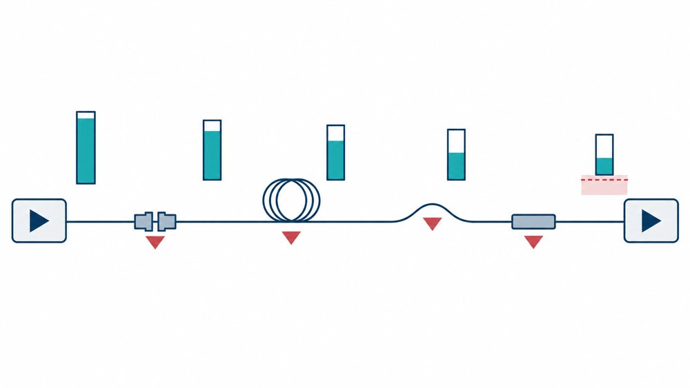
A complete link budget must also include connectors, pressure penetrators or rotary interfaces where fitted, splices, bend-induced loss, temperature and ageing effects, and engineering margin. The result must be compared with transmitter output, receiver sensitivity, data rate and required error performance. A 30 km length option is therefore not the same as 30 km of verified communication reach.
ZION’s published 0.35 dB/km at 1310 nm and 0.25 dB/km at 1550 nm are tighter than the general cabled-fiber maxima of 0.40 and 0.30 dB/km in ITU-T G.657:2024 for category A fiber. Project acceptance can request batch attenuation records, a finished-spool OTDR trace or an end-to-end insertion-loss report.
How to use the tensile ratings
The >150/>200 N values should be used only after the supplier defines the test basis. They are not automatically the allowable continuous tension, dynamic payout tension or connector load.
Rating name, gauge length, loading rate, hold time and failure criterion.
Allowable continuous and short-term tension plus the design safety factor.
Added attenuation under load and residual attenuation after unloading.
Finished-cable static/dynamic bend radii and the weakest termination or payout component.
Information required for a professional RFQ
Final underwater-platform integration requires a testable project specification. Include the following information in the RFQ or technical agreement:
- Model codes and the mapping between 0.50/0.65 mm diameter, linear mass, tensile rating, density and canister size;
- Maximum working depth, hydrostatic-pressure test, hold time, leakage criterion and wet-side connector rating;
- Maximum and recommended payout speed, allowable payout tension, payout direction and the meaning of disposable or reusable operation;
- Minimum static and dynamic bend radius for the finished cable and cable loaded in the canister;
- Complete mass in air, submerged weight, buoyancy, center of gravity, mounting pattern and 3D drawing;
- End-to-end insertion loss, return loss, OTDR trace, continuity and batch acceptance records;
- Wet-side connector model, channel count, mating interface, cycle life, pressure rating and material compatibility;
- PVC sheath requirements for seawater exposure, hydrolysis, abrasion, temperature cycling and long-term storage;
- Terminal wavelength, optical power budget, data interface, protocol, rate, power supply and target error performance;
- Length tolerance, end-lead allowance, warranty requirements and traceability documents.
FAQ
Does the 1–30 km range mean the system can communicate over 30 km?
No. It describes available loaded length. Usable reach depends on route geometry, terminal power budget, connection and bend loss, data rate and engineering margin.
Does G.657.A2 mean the finished cable can use a 7.5 mm bend radius?
Not automatically. The 7.5 mm value relates to bare-fiber macrobend performance in the standard. The finished cable and loaded-spool bend limits require separate supplier data.
Are FC/UPC and LC/UPC underwater connectors?
No. They identify optical interface and end-face formats; they do not establish water-tightness, pressure rating or wet-mate capability. The wet-side connection method must be specified separately.
What additional information matters most in an RFQ?
Prioritize platform type, mission length, depth and pressure, payout speed, allowable tension, optical interface, wavelength, power budget, installation envelope and acceptance tests.
Conclusion
ZION’s published length, diameter, linear mass, density and attenuation values support early trade-off studies, and the diameter-density-mass figures are mathematically consistent. Design release still requires depth and pressure ratings, dynamic payout limits, allowable working tension, finished-cable bend radius, complete submerged weight and acceptance methods.
Converting the public data into a project specification with model codes, test conditions, tolerances, drawing revisions and delivery records makes the system suitable for procurement, integration and acceptance.
References
Submit project parameters for configuration matching
Prepare the required length, platform type, depth, payout conditions, optical interfaces, link budget, installation envelope, quantity and acceptance requirements so the model, drawing and test records can be checked.
Request Project Support


