
1. Currently listed reference dimensions
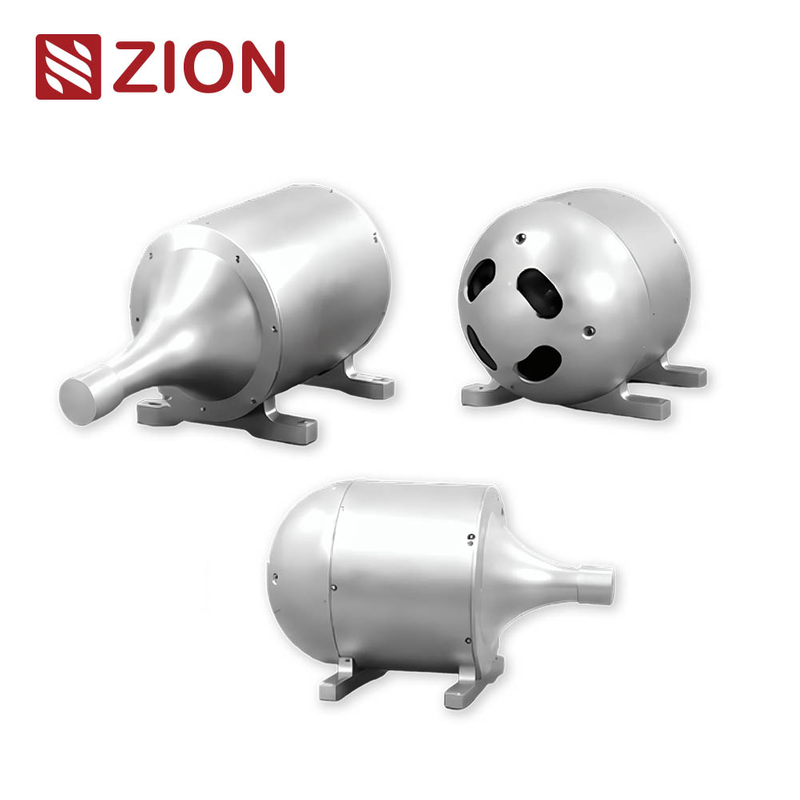
The ZION underwater fiber optic spool product page lists the following package sizes. They are useful for preliminary space studies, but the page does not identify the length, width and height axes, measurement datums or dimensional tolerances.
| Nominal fiber length | Listed dimensions | Integration status |
|---|---|---|
| 10 km | 237 × 180 × 152 mm | Reference envelope; confirm axis order, datum and tolerance |
| 20 km | 300 × 277 × 248 mm | Reference envelope; confirm axis order, datum and tolerance |
The same page lists 1–30 km length options, 0.5 mm and 0.65 mm cable diameters, unit masses of 248 g/km and 430 g/km, G.657.A2 single-mode fiber, and FC/UPC or LC/UPC optical interfaces. These rows do not establish which cable diameter belongs to each canister size or what envelope applies to a 30 km version.
The material row states “resin and metallic aluminum” for the can. Confirm whether these are alternative canister versions, a combined construction or materials assigned to separate parts.
2. What the controlled drawing should define
Before freezing the vehicle structure, request a revision-controlled 2D drawing and an exchangeable 3D model. The drawing package should remove every ambiguity that affects installation, payout or maintenance.
- Axis definitions, measurement datums, tolerances and maximum installation envelope.
- Mounting face, hole pattern, fasteners and allowable installation loads.
- Fiber outlet location, payout direction, guide geometry and required clearance.
- Service envelope for connectors, pigtails, seals, strain reliefs and installation tools.
- Mass, center of gravity and buoyancy change in the full, empty and intermediate payout states.
- Shipping restraint, pre-launch release, permitted orientation and error-proofing features.
- Rated depth or external pressure, pressure cycling, temperature, vibration, shock, immersion and corrosion conditions.
- Replacement, recovery and post-mission handling requirements.
3. Payout data is as important as static size
Fine optical cable is commonly pulled from a stationary pack or canister as the vehicle moves. Restricted clearance, path deflection, incorrect orientation or excessive speed can add optical loss, cause tangling or break the cable.
Specify initial, steady-state and peak payout tension, with test conditions and allowable variation.
Define minimum and maximum payout speed and the full length qualified at those conditions.
Confirm payout orientation, outlet angle, side-load limit, twist and dynamic bend radius.
Request full-length payout records at the agreed speed, load and environmental conditions.
The listed tensile strength of >150 N or >200 N is not automatically the continuous working tension, payout tension or allowable towing load. A breaking or short-duration tensile value needs a supplier-defined safety factor, test method and application condition before it can support a design load.
4. G.657.A2 does not define the complete cable bend radius
ITU-T G.657 defines A2 bend-insensitive single-mode fiber and specifies macrobending performance at defined wavelengths, radii and numbers of turns. The 7.5 mm value associated with G.657.A2 is a fiber design radius under specified test conditions.
It should not be copied directly into the mechanical drawing as the allowable radius for a jacketed micro-cable, pigtail, outlet guide or dynamic payout path. Use the supplier's static and dynamic minimum bend radii for the complete cable assembly, accounting for both mechanical life and added optical loss.
5. Separate the optical connector from the underwater pressure boundary
FC/UPC and LC/UPC identify connector families and UPC end-face geometry. They do not by themselves establish that a connection is wet-mateable or rated for external water pressure.
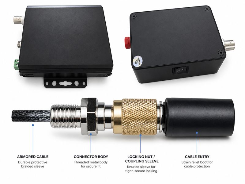
- Identify whether the FC/UPC or LC/UPC connection is inside a dry pressure housing or exposed to water.
- Define whether the underwater boundary uses a wet-mate connector, a dry-mate connector installed before launch, or a penetrator with a molded pigtail.
- State rated depth, working and test pressure, sealing method, hold time, cycle count and mating life.
- Count every adapter, splice and connector in the end-to-end optical configuration.
6. Fiber length, package size and communication reach are different values
The listed 1–30 km fiber range is not a guaranteed vehicle radius from the host platform. Lead length, a non-straight route, obstacle avoidance, slack, reserve and fiber left inside the canister all reduce usable reach.
| Wavelength | Listed attenuation coefficient | Fiber-only loss at 30 km |
|---|---|---|
| 1310 nm | ≤0.35 dB/km | Up to approximately 10.5 dB |
| 1550 nm | ≤0.25 dB/km | Up to approximately 7.5 dB |
Connector, splice, bend, payout-state and engineering margins are additional. Select the final length only after both the mechanical deployment case and the transceiver optical power budget have been checked.
A longer 40–90 km concept requires its own traceable model, configuration drawing, optical budget and full-length payout evidence before it can be treated as a deliverable single-canister or multi-canister configuration.
7. Standard, customized and multi-canister configurations
A standard configuration should be supported by a controlled supplier specification, drawing and acceptance method. Changing fiber length, cable diameter, winding process, outlet geometry, material, interface or pressure design may change the envelope, mass, center of gravity, payout tension, optical loss and qualification scope.
Connecting multiple canisters or adding intermediate joints is not simply a matter of adding capacity. Every joint adds optical loss and a failure interface, while multiple canisters introduce payout-sequence, load-transfer, entanglement and separation-control requirements. Define the system architecture, timing, mechanical interfaces and end-to-end test before approving the arrangement.
8. Recommended design-review exit criteria
Use measurable records rather than a generic product description when releasing the purchase or mechanical design.
- The ordered model, fiber length, cable diameter and drawing revision are traceable to one another.
- Maximum envelope, hole pattern, tolerances, mass and center of gravity are confirmed in writing.
- Payout direction, clearance, tension, speed and dynamic bend radius have specified values.
- Rated depth, pressure test, sealing boundary and underwater connection method are defined.
- The optical budget includes fiber, connectors, splices, bends and engineering margin.
- The prototype or delivered unit completes the agreed dimensional, optical, pressure and payout tests.
- Deviations and design changes remain under revision control.
9. Frequently asked questions
Are the listed 10 km and 20 km dimensions sufficient for mechanical integration?
No. They support preliminary layout, but the approved drawing still needs axis definitions, datums, tolerances, mounting details, outlet geometry, connector projection, mass and center of gravity.
Does 30 km of fiber provide a 30 km vehicle operating radius?
No. Lead length, route geometry, obstacles, slack, reserve and fiber left in the canister reduce usable reach. The optical power budget must also support the complete link.
Can the listed tensile strength be used as payout tension?
No. Breaking or short-duration tensile strength is not the same as continuous working or payout tension. The project specification needs supplier-defined initial, steady-state and peak payout limits.
Are FC/UPC and LC/UPC underwater connectors?
Not by themselves. They identify optical connector families and UPC end-face geometry. The underwater boundary still requires a documented wet-mate, dry-mate or penetrator solution with a stated depth and pressure rating.
10. Reference standards and product data
- ZION Underwater Fiber Optic Spool for ROV/UUV Communication
- ITU-T G.657: Characteristics of a bending-loss insensitive single-mode optical fibre and cable
- IEC 60794-1-1:2023: Optical fibre cables — Generic specification — General
Prepare a project-specific canister configuration
Send the required fiber length, cable diameter, installation envelope, mounting orientation, payout speed, tension limits, operating depth, connector boundary and acceptance-test requirements for engineering review.
Request Project Support


