
Direct selection answer
A reliable selection cannot be made from “1310/1550 nm, FC port, network port and serial port” alone. Start with a matched end-to-end architecture, then verify the transmitter and receiver optical ranges, passive path loss, service protocol and subsea connection method.
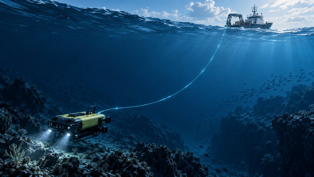
The current ZION underwater fiber optic spool system lists transmitting and receiving terminals, 1310 nm/1550 nm options, FC optical ports, network and serial ports, and a watertight wired connection. These details establish the available configuration direction; the final model still needs a controlled datasheet and approved interface drawing.
Define the link architecture first
The notation “1310 nm/1550 nm” shows two wavelength options, but it does not define how a terminal pair transmits and receives. Identify one of the following architectures before specifying the equipment.
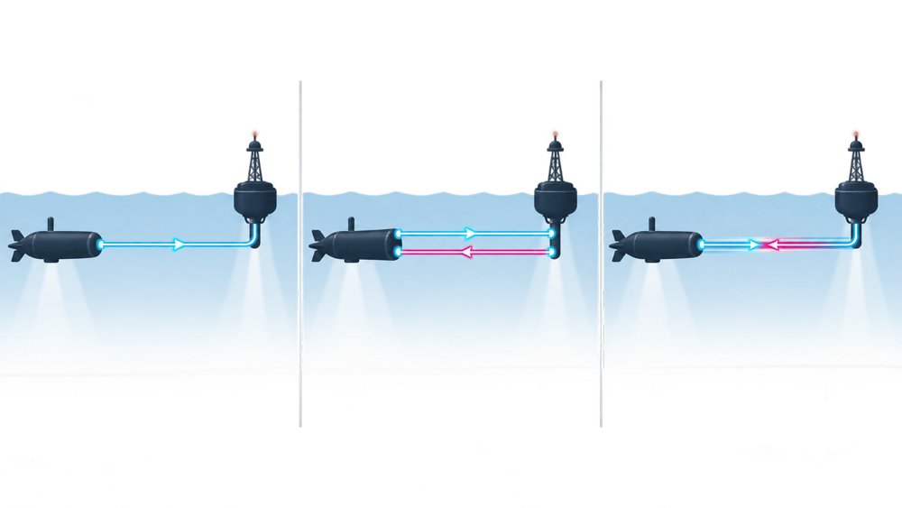
One terminal transmits and the other receives, normally at the same nominal wavelength.
Each direction uses a separate fiber. Both terminals require optical transmit and receive functions.
A matched pair uses complementary wavelengths, such as end A TX 1310/RX 1550 nm and end B TX 1550/RX 1310 nm.
Record TX/RX wavelength at each end, fiber count, data direction and whether WDM components are integrated.
Choose between 1310 nm and 1550 nm
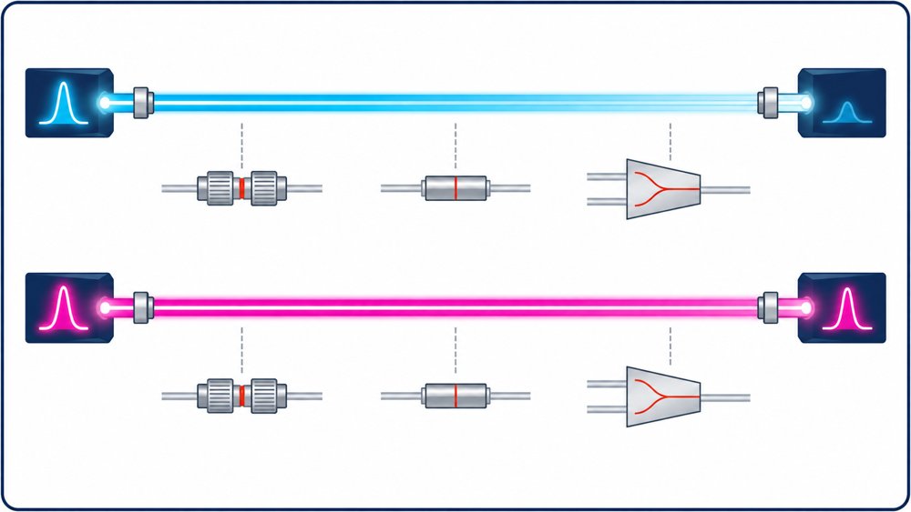
The published cabled-fiber attenuation limits are ≤0.35 dB/km at 1310 nm and ≤0.25 dB/km at 1550 nm. These are plausible values for the specified G.657.A2 product, but they should be treated as product values rather than universal limits for every G.657.A2 cable.
| Wavelength | Published maximum attenuation | 30 km fiber-only loss | Selection context |
|---|---|---|---|
| 1310 nm | ≤0.35 dB/km | 10.5 dB | Near the zero-dispersion wavelength of conventional single-mode fiber. |
| 1550 nm | ≤0.25 dB/km | 7.5 dB | Lower fiber attenuation; dispersion and deployed bend conditions still require evaluation. |
The 1550 nm option reduces fiber-only attenuation by 3 dB in this example, but it is not automatically the better choice. Terminal reach and the complete optical operating window should drive the decision for a 1–30 km project.
Verify the optical power budget and overload limit
Use minimum transmitter output and receiver sensitivity to establish the maximum passive loss that the equipment can tolerate.
Estimate the path loss separately:
The 7.5 dB or 10.5 dB value is only the fiber contribution over 30 km. Check the receiver maximum input or overload point as well: long links can have insufficient power, while short links can overdrive the receiver. A usable terminal specification therefore needs minimum and maximum launch power, receiver sensitivity, overload and a stated margin.
Separate the optical connector from the subsea pressure boundary
The terminal table states “FC,” while the spool specification states “FC/UPC or LC/UPC.” Confirm whether the terminal interface is FC/UPC or FC/APC, whether an adapter or patch lead is required, and the insertion-loss and return-loss allowance for each mated connection.
A standard FC/UPC or LC/UPC interface is not a subsea connector by itself. If the connection is exposed to external water pressure, define whether the design uses a pressure penetrator, dry-mate connector or subsea wet-mate connector. Specify rated depth or pressure, hold time, mating condition, materials, mating cycles and saltwater corrosion requirements.
Define Ethernet and serial services precisely
“Network port” does not establish 100BASE-TX, 1000BASE-T or another rate, and it does not prove transparent transport. Record the Ethernet rate, connector, auto-negotiation, duplex mode, VLAN and multicast handling, jumbo-frame requirement, latency, packet-loss limit, isolation and surge/ESD requirement.
“Serial port” does not identify RS-232, RS-422 or RS-485. Record baud rate, data bits, parity, stop bits, half/full duplex, termination, isolation, pinout and direction. Transparent serial transport and protocol conversion such as Modbus conversion are different functions.
Project information needed before ordering
A purchase-ready terminal package should include the following controlled information:
- TX/RX wavelength at each end and the one-fiber or two-fiber architecture.
- Minimum and maximum launch power, receiver sensitivity and receiver overload.
- Supported service rate, target BER, latency and protocol transparency.
- Input-voltage range, peak power, start-up behavior and electrical protection.
- Terminal size, mass, mounting, housing material and corrosion requirements.
- Operating depth or external pressure, hydrostatic test method and hold time.
- Operating/storage temperature, shock, vibration and sealing requirements.
Underwater terminal confirmation table
Use this table to align the underwater and surface-side equipment before quotation or technical approval.
| Item | Underwater end | Surface or shore end |
|---|---|---|
| Link architecture | One-way, two-fiber duplex or one-fiber BiDi; fiber count | Matched architecture |
| Optical interface | TX/RX wavelength, Tx min/max, Rx sensitivity/overload, connector and polish | Complementary optical parameters and interface |
| Service interface | Ethernet or serial standard, rate, protocol, port count and direction | Matching service definition |
| Optical path | Length, connection/splice/WDM loss and engineering margin | Approved receiver power window |
| Power | Input range, consumption, protection, connector and pinout | Input range, consumption and grounding |
| Environment | Depth/pressure, hold time, temperature, corrosion, shock and vibration | Temperature, humidity and ingress protection |
| Mechanical integration | Size, mass, mounting, penetrator or subsea connection | Rack, wall or desktop arrangement |
| Acceptance | Datasheet, ICD, serial number and test record | End-to-end BER and service test |
Technical references
- ZION Underwater Fiber Optic Spool for ROV/UUV Communication
- ITU-T G.657 (08/2024): Characteristics of a bending-loss insensitive single-mode optical fibre and cable
- FOA: Calculating Fiber Optic Loss Budgets
- IEC 60794-1-1:2023: Optical fibre cables—Generic specification
- TE Connectivity: Optical Wet-Mate Connectors
Prepare a matched terminal specification
Send the required link length, fiber count, TX/RX wavelengths, Ethernet or serial definition, operating depth, power input and connector requirements for project review.
Request Project Support


