
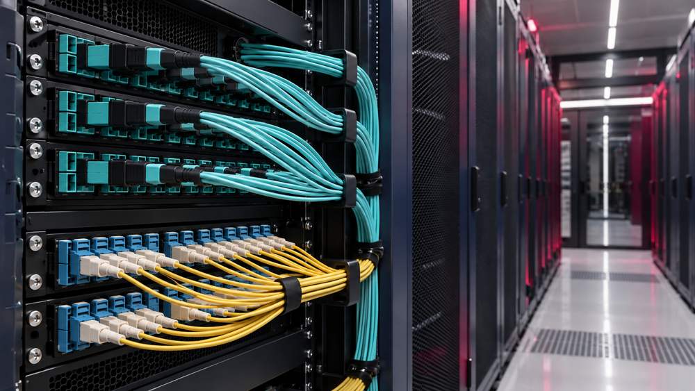
Installed cables, populated patch panels, and active switch ports are signs of progress. Project acceptance requires something more specific: evidence that every delivered fiber path meets the approved design and that its test records match the final installation.
For AI data centers using dense multifiber connections and parallel optics, that evidence must be traceable down to individual fibers and ports. However, “AI data center” does not define a universal set of fiber acceptance limits. The optical interface, cabling configuration, and applicable project standards determine what needs to be tested and what constitutes a pass.
This checklist focuses on passive fiber cabling inside the data center. It helps procurement teams, project managers, and engineers define the acceptance scope, review test results, and prepare a usable handover package. Transceiver and network performance validation belong in the network commissioning plan.
1. Define the Application and Test Boundaries
“Supports 800G” is not a complete cabling specification. Different optical interfaces can require different fiber counts, connector configurations, reach limits, and loss budgets.
For example, Cisco’s OSFP-800G-DR8 uses eight pairs of single-mode fibers with dual MPO-12 APC connectors and supports links up to 500 m. Its OSFP-2X400G-FR4 uses two duplex fiber connections and supports reach up to 2 km. These are specific product configurations, not universal connector requirements for every 800G module. See the Cisco OSFP 800G transceiver data sheet.
Before placing an order or starting field testing, document the following:
| Item | What the acceptance plan should specify |
|---|---|
| Target application | Optical interface, approved transceiver model or compatibility specification, and breakout operating mode |
| Fiber path | Fiber category, connector type and polish, multifiber connector pin configuration, cassettes, and fiber mapping |
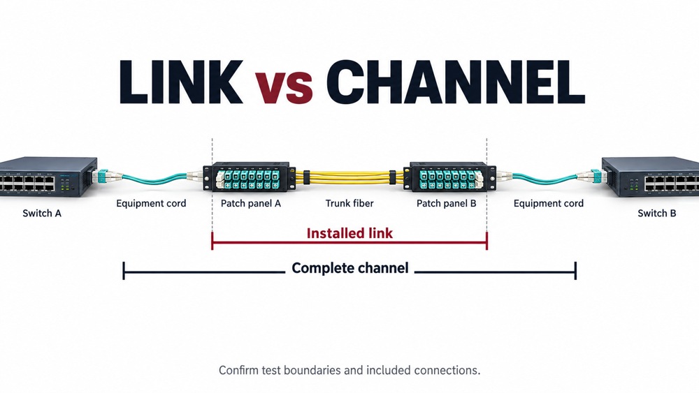
| Test boundaries | Whether the test covers a component, installed link, or complete channel including equipment cords; include a connection diagram |
| Acceptance criteria | Standard editions, application requirements, cabling loss budget, wavelengths, directions, reference method, limits, and required margin |
| Responsibilities | Test coverage, report format, exception review, corrective work, retesting, and final sign-off |
Different standards address different parts of the process. ISO/IEC 14763-3:2024 covers inspection and testing of installed optical fiber cabling. IEC 61280-4-1 addresses multimode attenuation measurement, while IEC 61280-4-2:2024 addresses single-mode attenuation and optical return loss measurement. IEC 61300-3-35:2022 addresses connector end-face inspection. Identify the editions and amendments adopted by the project rather than relying on a general statement of “compliance with international standards.”
2. Establish the Fiber Acceptance Checklist
The following table provides a starting point for a project acceptance plan. It is not a universal list of mandatory tests for every installation.
| Acceptance item | What to verify | Evidence to retain |
|---|---|---|
| Components, labels, and fiber count | Fiber category, installed components, terminated fiber count, and spare capacity match the design | As-built inventory, component identifiers, and port schedule |
| Length and routing | Measured link length and final channel length meet design and application requirements | Length results, measurement method, route records, and relevant instrument settings |
| Continuity and polarity | Each fiber reaches its intended destination and matches the approved port configuration | End-to-end fiber map and polarity results |
| End-face inspection and cleaning | Mating surfaces are inspected, contamination is addressed, and exceptions follow the approved process | Inspection results, exception images, and reinspection records |
| Per-fiber insertion loss | Each fiber meets the applicable limit at the specified wavelengths and directions | Measured loss, limit, margin, and reference settings |
| Reflection performance, where required | Component return loss, link optical return loss, or event reflectance meets the relevant requirement | Results identifying the measured object, method, wavelength, direction, and limit |
| OTDR testing, where required | Required event characterization, baseline recording, or fault investigation is complete | Native traces, event tables, settings, and corrective-action records |
| Final documentation | Results correspond to the final installed configuration | Coverage matrix, change records, open-item register, and sign-off documents |
“Where required” means the scope must be established before testing. Tests required by the applicable standard or contract cannot be omitted at the field team’s discretion.
3. Check Insertion Loss Against the Correct Limits
Insertion loss (IL) describes the reduction in optical power through the path under test, expressed in decibels. Under comparable measurement conditions, a lower value means less loss.
Two constraints need attention: the cabling loss budget, based on fiber length, connections, splices, and other passive components; and the channel loss allowance and operating conditions of the target optical interface. The installation must satisfy both. A pass against a generic cabling limit does not, by itself, establish support for a particular application. Fluke Networks explains this relationship in its loss-budget guidance.
Before comparing results and limits, confirm that they refer to the same boundaries, wavelengths, and reference method. An installed-link result does not automatically represent a complete channel containing additional equipment cords and connections.
For example, if an approved test limit is 1.50 dB and a fiber measures 1.42 dB, the reported margin is 0.08 dB. These figures illustrate how to read a report; they are not universal AI data center limits. That margin alone does not establish long-term stability. Required reserve margin and the treatment of borderline measurements should follow the decision rules agreed before testing, including how measurement uncertainty is handled.
Specify per-fiber testing for all terminated fibers within the handover scope, including terminated spares. Average trunk loss or a small sample of passing fibers cannot replace the agreed coverage.
4. Make Loss Measurements Repeatable
A valid calibration certificate is only one part of a reliable field measurement. Test reference cord condition, reference settings, and optical launch conditions also affect results.
The test plan should identify the reference method, test reference cords, and adapter configuration. Retain reference-setting and cord-verification records. Where applicable, use the standards-preferred one-cord reference method. Other configurations require a suitable method and a clear statement of which connections are included in the measurement.
For multimode attenuation testing, the launch must meet the encircled flux (EF) conditions required by the adopted method. Controlling the launch helps make measurements comparable across test setups. Fluke Networks’ guidance on reference methods and EF explains why these conditions matter.
Common test wavelength pairs are 850/1300 nm for multimode and 1310/1550 nm for single-mode fiber, as illustrated by commercial fiber test sources. The required wavelengths and directions depend on the adopted standard, application, and cabling configuration. Test wavelengths should not be confused with the operating wavelengths of the transceiver.
If a change to the test setup affects the reference, verify it again and reset it when required by the approved procedure and instrument instructions. Investigate unexpected negative loss, unusually low readings, or inconsistent retest results before accepting them.
5. Verify Length, Fiber Count, and Polarity Separately
A passing loss result does not replace a length check. Applications can impose maximum reach limits as well as loss limits. Confirm the final channel length and retain evidence of the installed fiber category. For measurements derived from propagation time, record the relevant refractive-index or propagation settings. Fluke Networks’ application-limit guidance highlights the need to consider distance alongside loss.
Fiber-count records should distinguish the design count, populated fibers, terminated fibers, fibers in use, and spares. If a 144-fiber MPO trunk initially uses 96 fibers and the remaining 48 are delivered as terminated spares, include those spares in the specified acceptance testing. Record unterminated reserve fibers separately, with an inspection method appropriate to their delivery condition.
For MPO systems, verify the relationship between connector positions, populated fibers, and application lanes. A Type A, Type B, or Type C label on one cord does not prove that the complete channel has the correct polarity. Trunks, cassettes, adapters, and patch cords work together to determine the final mapping. See Fluke Networks’ explanation of MPO polarity.
Handover records should trace each fiber from the rack, panel, port, and fiber position at one end to the corresponding destination at the other. Breakout configurations also require a match to the approved equipment ports and lane assignments.
6. Inspect Both Mating End Faces and the Full Contact Area
New packaging and dust caps do not establish that a connector is clean. Use a consistent workflow: inspect, clean when necessary, reinspect, then connect. Apply it to both mating end faces, including the patch-panel side. Connector inspection is also a core part of EXFO’s data center testing workflow.
For rectangular ferrules such as those used in MPO connectors, inspect the full ferrule contact surface for contamination, as well as the relevant inspection zones on individual fiber end faces. Looking only at the fibers currently carrying traffic can miss contamination elsewhere on the mating surface. The IEC 61300-3-35:2022 official overview distinguishes whole-contact-area cleanliness from scratch and defect inspection in the fiber core and cladding zones.
Visual inspection and optical performance measurements provide complementary evidence. If a visual exception remains after loose contamination has been removed, retain images and follow the review process defined by the applicable standard and contract. Any acceptance decision should use optical performance evidence relevant to the affected component and have an identified approval responsibility. A single end-to-end loss pass is not sufficient grounds to disregard a connector inspection exception. Fluke Networks discusses the 2022 inspection changes and their optical-performance provisions here.
7. Distinguish Return Loss, Optical Return Loss, and Reflectance
Reflection-related results may all use decibels while describing different measurement scopes.
| Metric | Measurement scope | How to read it |
|---|---|---|
| Return loss (RL) | A specified component or connection | When expressed as a positive dB value, a larger number means a smaller returned-power ratio |
| Optical return loss (ORL) | A defined optical path, including reflection and backscatter contributions | When expressed as a positive dB value, a larger number means a smaller total returned-power ratio |
| Event reflectance | An individual reflective event, such as a connection | When expressed as a negative dB value, a more negative number means less reflection |
With the same measured object, reference plane, and power-ratio definition, 50 dB return loss and −50 dB reflectance represent the same power ratio. However, a component RL value, a whole-link ORL result, and an individual OTDR event’s reflectance are not interchangeable. Fluke Networks explains return loss and reflectance.
Define which evidence the application requires, the measurement method and limits, and whether field measurement is necessary. A typical factory RL specification does not establish the reflection performance of the installed channel.
8. Use OTDR Testing to Characterize and Locate Events
Complete end-to-end loss testing using the approved optical loss test set (OLTS) or light-source-and-power-meter method. An optical time-domain reflectometer (OTDR) provides event locations and trace information that help investigate connections, splices, bends, and breaks. Its trace does not replace the end-to-end loss report required by the acceptance plan. Fluke Networks describes the complementary roles of OLTS and OTDR testing.
Data center links can be short, with connections spaced more closely than an OTDR can resolve under a given configuration. Select appropriate launch and receive fibers, pulse widths, range, and acquisition settings, accounting for both event and attenuation dead zones. The absence of a separately resolved event does not prove that no connection or defect exists at that location. See Fluke Networks’ Tier 1 and Tier 2 testing guidance.
Where bidirectional event-loss analysis is required, match the same events in both directions and process the results according to the specified method. This helps account for backscatter differences. A “gainer” on a one-direction trace does not mean a passive connection is amplifying the signal. Fluke Networks illustrates bidirectional measurement and gainer events.
Set OTDR coverage through the applicable standards and project requirements. Retain the agreed native traces, settings, and event tables rather than screenshots alone.
9. Match the Handover Package to the Final Installation
Factory testing establishes whether a component met its order specifications before shipment. Field acceptance establishes whether the installed fiber path meets the project requirements. Component identifiers and link identifiers should connect these records, but the two reports serve different purposes.
Before sign-off, review the following:
- As-built drawings, port schedules, fiber maps, and component inventories that match the installation.
- A test coverage matrix distinguishing passed, untested, pending-correction, and approved-deviation items.
- Results showing measured values, limits, margins, wavelengths, and directions, plus the agreed native data files.
- Instrument models, serial numbers, calibration status, test dates, operator details, and configurations.
- Reference-setting, test reference cord verification, and connector inspection exception records.
- Component replacements, patching changes, corrective work, retest results, and sign-off responsibilities.
If a patch cord, cassette, or other component changes after testing, identify the affected paths and complete the required retesting. A trunk-only report does not automatically cover connections and equipment cords added later.
Passive fiber acceptance also does not complete AI network commissioning. Transceiver compatibility, port operating modes, bit-error performance, forward error correction (FEC) metrics, and operational testing require their own defined validation plan.
Define the Deliverables with ZION Before Procurement
When discussing a data center fiber connectivity project with ZION, include the target optical interface, fiber category, connection layout, fiber mapping, and acceptance requirements in your inquiry. Use the quotation and technical confirmation process to establish the supplied components, accompanying test records, and responsibility for field testing, corrective work, and final approval.
For each agreed report, confirm its fields, identification scheme, and delivery format before the order is finalized. Clear requirements give procurement a defined scope, installers and test teams a common acceptance basis, and operations staff records they can use when maintaining or expanding the network.
Plan Your Fiber Acceptance Requirements
Share your optical interface, cabling layout, quantities, fiber mapping, and test requirements with ZION to define the component and documentation scope for your project.
Request Project Support


